6.2.8 POSITIONING THE
OUTLET TERMINALS
The outlet terminals for forced-draught
appliancesmay belocatedin theexter-
nalperimeterwallsofthebuilding.
To provide some indications of possible
solutions,tobeobserved,withreference
to the type of building shown in fig. 14
and14/a,givestheminimumdistances.
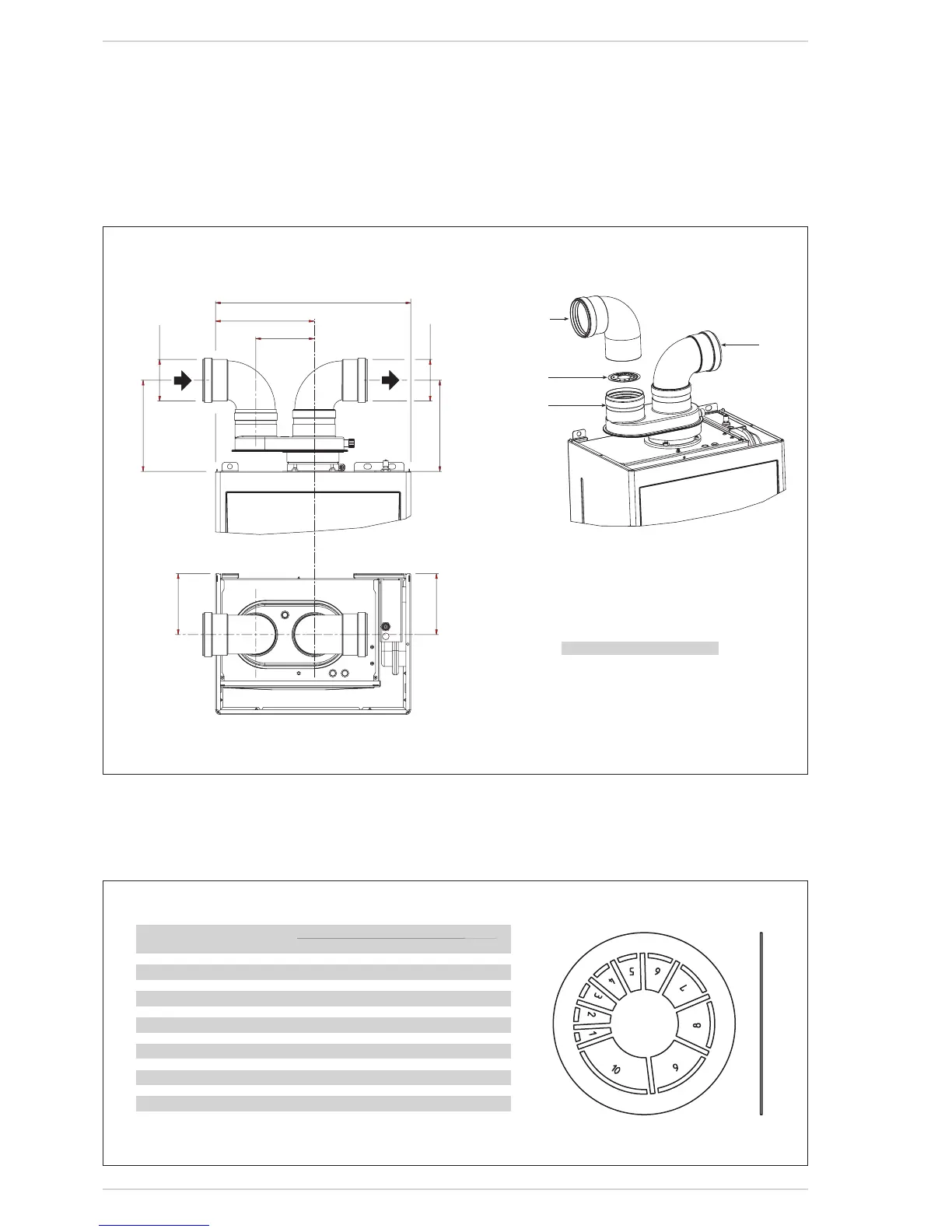
6.2.7.1 Air/combustion
products divider
The air/combustion products divider
cod.8093020 (fig. 12) is supplied with a
diaphragm,segmentsmustberemoved,
depending on the maximum head loss
accepted in both ducts, as indicated in
fig.12/a.
6.2.7.2 Outlet systems
Thediagramsinfig.13illustrateanum-
ber of examples of different types of
separateoutlets.
No. segments Total load loss
to remove mm H2O Pa
none 0÷0.8 0÷7.85
No.1 0.8÷1.5 7.85÷14.7
No.1e2 1.5÷2.4 14.7÷23.5
fromNo.1to3 2.4÷3.2 23.5÷31.4
fromNo.1to4 3.2÷4.0 31.4÷39.2
fromNo.1to5 4.0÷4.8 39.2÷47.1
fromNo.1to6 4.8÷5.6 47.1÷54.9
fromNo.1to7 5.6÷6.5 54.9÷63.7
fromNo.1to8 6.5÷7.3 63.7÷71.6
fromNo.1to9 7.3÷7.8 71.6÷76.5
fromNo.1to10 7.8÷8.4 76.5÷82.4
withoutdiaphragm 8.4÷9.5 82.4÷93.2