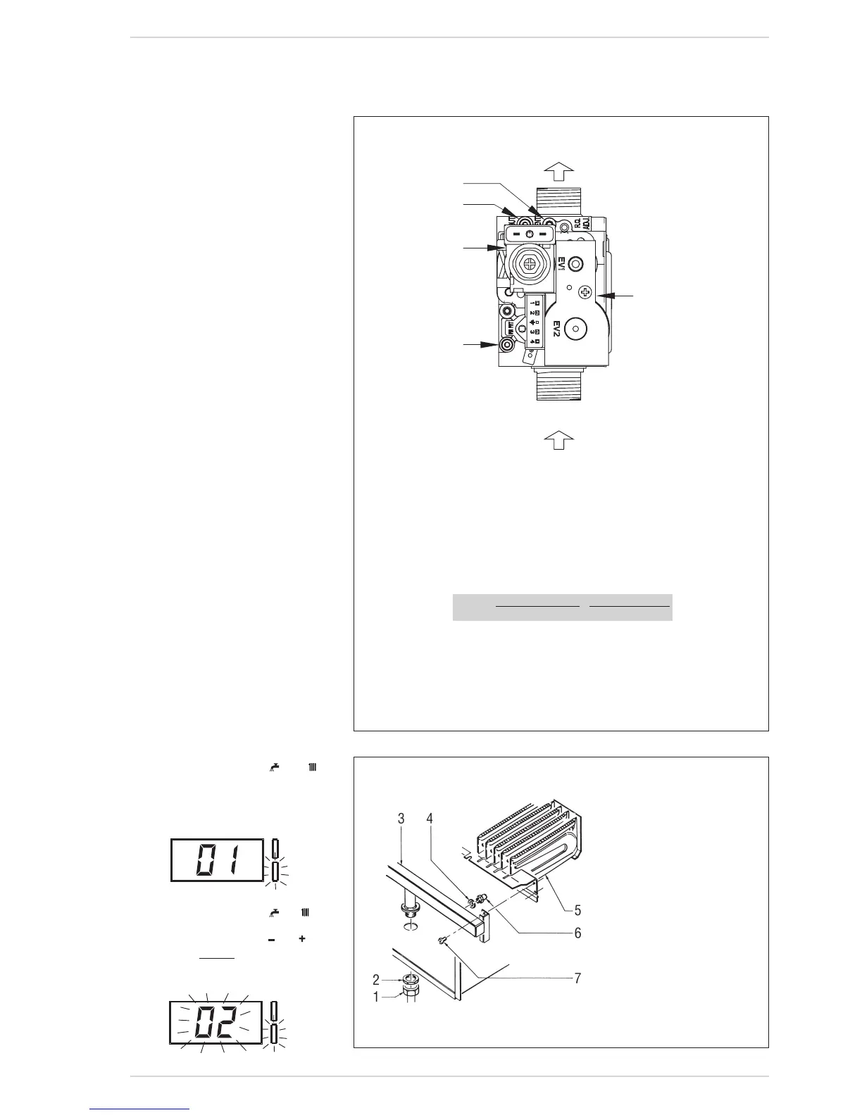
6.4.1 GAS VALVE
The boilers are equipped standard with
theSIT845SIGMAgasvalve(fig.22).
The gas valve is set at two pressure
values:maximumandminimum.
Accordingtothetypeofgasburnt,these
correspondto thevaluesgiven inTable
4.
The gas pressures at the maximum
and minimum values, are factory set.
Consequentlytheymustnotbealtered.
The gas valve will require resetting on
conversion to another gas(Natural gas
toLPG).
6.4.2 GAS CONVERSION
This operation must be performed by
authorised personnel using original
Sime components.
To convert from natural gas to LPG or
viceversa,performthefollowingopera-
tions(fig.23):
– Close the gas cock and isolate the
boilerselectricalsupply.
– Disassembletheburnermanifold(3).
– Replacethemainnozzles(6)supplied
in a kit, inserting the copper washer
(4).Useaø7spannertoperformthis
operation.
– Configurethenewfuelasindicatedin
point6.4.2.1
– For calibrating the maximum and
minimum gas pressure values, see
point6.4.2.2.
–Fixthelabeltothedataplateshowing
theNewgasconfiguration.
NOTE: Ensure that on reassembly all
seals are replaced as require, and the
tightness tested, using a suitable leak
detection fluid.
6.4.2.1 New fuel configuration
Accesstheparameterssectionbypres-
singthecontrolpanelkeys(
Fig.23
KEY
1 Swivelconnection1/2”
2 Locknut1/2”
3 Burnermanifold
4 Washerø6.1
5 Burners
6 NozzleM6
7 Screw
WARNING: To ensure a perfect
seal, always use the washer (4)
supplied in the kit when repla-
cing nozzles, even in burner
units for which it is not speci-
fied.
Fig.22
KEY
1 Modulator
2 EV1-EV2coils
3 Pressureinletupstream
4 Pressureinletdownstream
5 VENTpressure
TABLE 4
Output BurnerpressurekPa ModulatorcurrentmA
NG LPG NG LPG
Maximum 0,85 2,50 130 165
Minimum 0,04 0,33 0 0