DETAILED
0
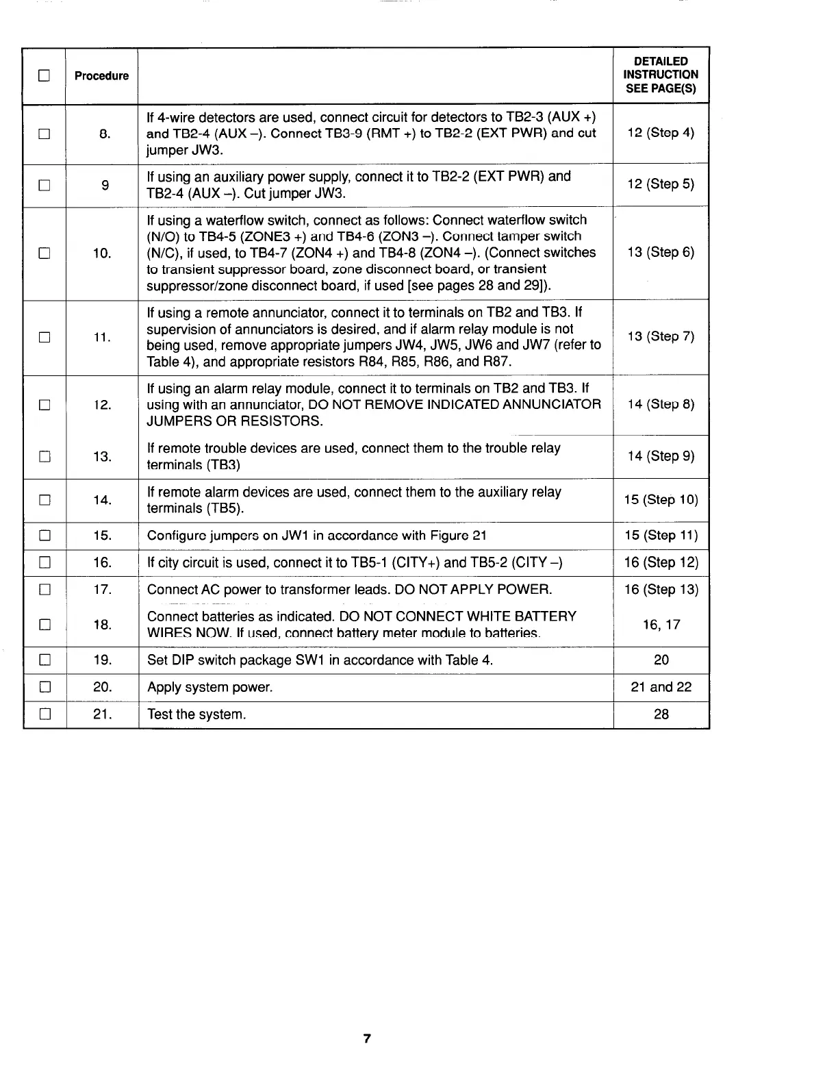
Procedure
INSTRUCTION
SEE PAGE(S)
If 4-wire detectors are used, connect circuit for detectors to TB2-3 (AUX +)
0
8.
and TB2-4 (AUX -). Connect TB3-9 (RMT +) to TB2-2 (EXT PWR) and cut
12 (Step 4)
jumper JW3.
0
9
If using an auxiliary power supply, connect it to TB2-2 (EXT PWR) and
TB2-4 (AUX -). Cut jumper JW3.
12 (Step 5)
If using a waterflow switch, connect as follows: Connect waterflow switch
(N/O) to TB4-5 (ZONE3 +) and TB4-6 (ZON3 -). Connect tamper switch
0
10.
(N/C), if used, to TB4-7 (ZON4 +) and TB4-8 (ZON4 -). (Connect switches
13 (Step 6)
to transient suppressor board, zone disconnect board, or transient
suppressor/zone disconnect board, if used [see pages 28 and 291).
If using a remote annunciator, connect it to terminals on TB2 and TB3. If
0 11.
supervision of annunciators is desired, and if alarm relay module is not
being used, remove appropriate jumpers JW4, JW5, JW6 and JW7 (refer to
13 (Step 7)
Table 4), and appropriate resistors R84, R85, R86, and R87.
If using an alarm relay module, connect it to terminals on TB2 and TB3. If
0
12. using with an annunciator, DO NOT REMOVE INDICATED ANNUNCIATOR
14 (Step 8)
JUMPERS OR RESISTORS.
0
13.
If remote trouble devices are used, connect them to the trouble relay
terminals (TB3)
14 (Step 9)
0
14.
If remote alarm devices are used, connect them to the auxiliary relay
terminals (TB5).
15 (Step 10)
0
15.
Configure jumpers on JWl in accordance with Figure 21 15 (Step 11)
0
16. If city circuit is used, connect it to TB5-1 (CITY+) and TB5-2 (CITY -) 16 (Step 12)
0
17.
Connect AC power to transformer leads. DO NOT APPLY POWER. 16 (Step 13)
0
18.
Connect batteries as indicated. DO NOT CONNECT WHITE BATTERY
WIRES NOW. If used, connect battery meter module to batteries.
16,17
El
19. Set DIP switch package SW1 in accordance with Table 4. 20
0
20. Apply system power. 21 and 22
01 21.
1 Test the system.
I
28
7