CONTROL PANEL TERMINAL CONNECTIONS (REFER TO WIRING DIAGRAM 841-610)
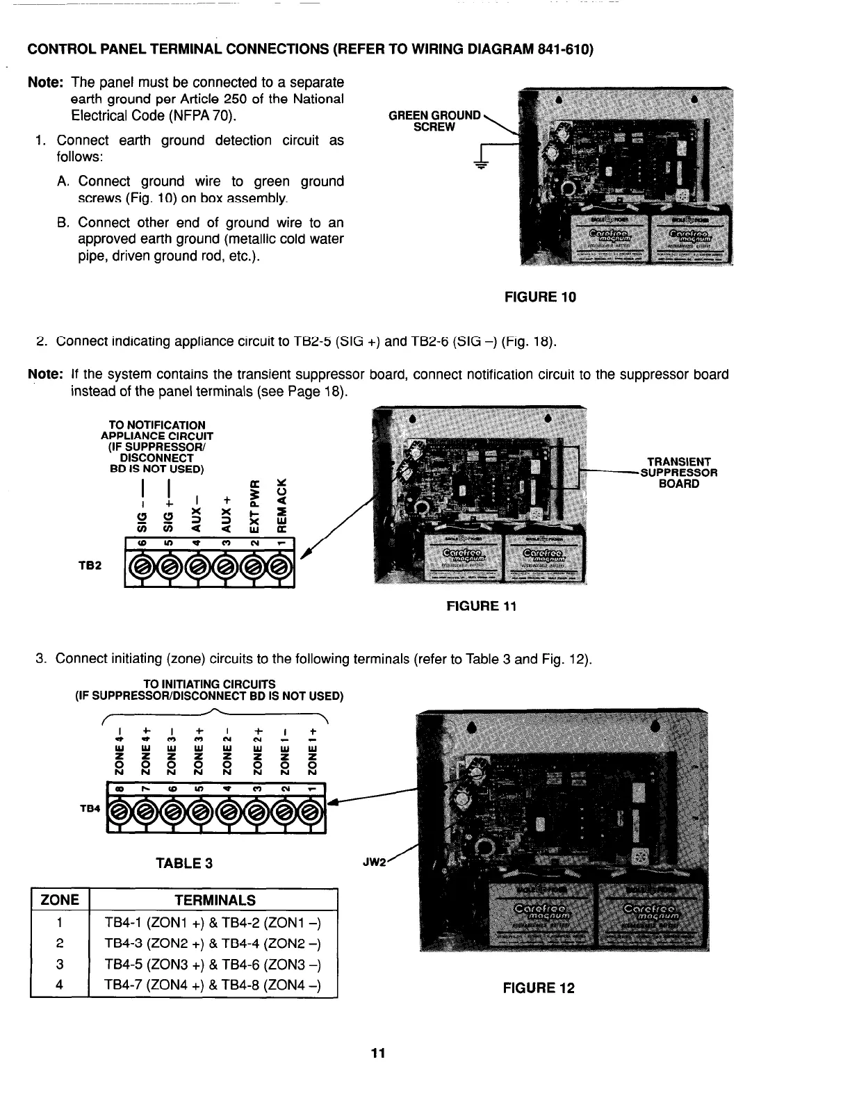
Note: The panel must be connected to a separate
earth ground per Article 250 of the National
Electrical Code (NFPA 70).
1. Connect earth ground detection circuit as
follows:
A.
B.
Connect ground wire to green ground
screws (Fig. 10) on box assembly.
Connect other end of ground wire to an
approved earth ground (metallic cold water
pipe, driven ground rod, etc.).
GREEN GROUND
SCREW
FIGURE 10
2. Connect indicating appliance circuit to TB2-5 (SIG +) and TB2-6 (SIG -) (Fig. 18).
Note: If the system contains the transient suppressor board, connect notification circuit to
instead of the panel terminals (see Page 18).
TO NOTIFICATION
APPLIANCE CIRCUIT
(IF SUPPRESSOR/
DISCONNECT
BD IS NOT USED)
the suppressor board
TRANSIENT
FIGURE 11
3. Connect initiating (zone) circuits to the following terminals (refer to Table 3 and Fig. 12).
TO INITIATING CIRCUITS
(IF SUPPRESSOR/DISCONNECT BD IS NOT USED)
TABLE 3
JW2
/
ZONE TERMINALS
1 TB4-1 (ZONl +) & TB4-2 (ZONl -)
2 TB4-3 (ZON2 +) & TB4-4 (ZON2 -)
3
TB4-5 (ZON3 +) & TB4-6 (ZON3 -)
4 TB4-7 (ZON4 +) & TB4-8 (ZON4 -)
FIGURE 12
11