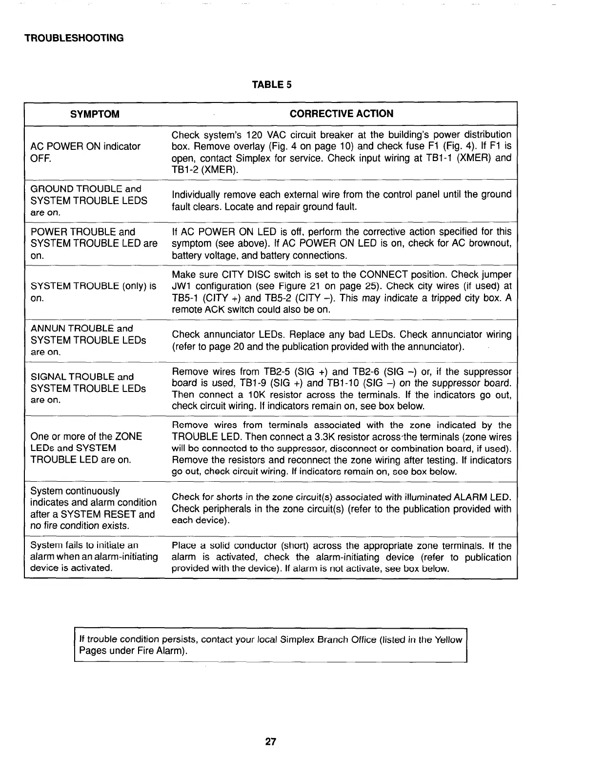
TROUBLESHOOTING
TABLE 5
SYMPTOM
CORRECTIVE ACTION
I
AC POWER ON indicator
OFF.
Check system’s 120 VAC circuit breaker at the building’s power distribution
box. Remove overlay (Fig. 4 on page 10) and check fuse Fl (Fig. 4). If Fl is
open, contact Simplex for service. Check input wiring at TBl-1 (XMER) and
TBl-2 (XMER).
GROUND TROUBLE and
SYSTEM TROUBLE LEDS
are on.
Individually remove each external wire from the control panel until the ground
fault clears. Locate and repair ground fault.
POWER TROUBLE and
If AC POWER ON LED is off, perform the corrective action specified for this
SYSTEM TROUBLE LED are
symptom (see above). If AC POWER ON LED is on, check for AC brownout,
on.
battery voltage, and battery connections.
Make sure CITY DISC switch is set to the CONNECT position. Check jumper
SYSTEM TROUBLE (only) is JWl configuration (see Figure 21 on page 25). Check city wires (if used) at
on.
TB5-1 (CITY +) and TB5-2 (CITY -). This may indicate a tripped city box. A
remote ACK switch could also be on.
ANNUN TROUBLE and
SYSTEM TROUBLE LEDs
are on.
Check annunciator LEDs. Replace any bad LEDs. Check annunciator wiring
(refer to page 20 and the publication provided with the annunciator).
SIGNAL TROUBLE and
SYSTEM TROUBLE LEDs
^“^ ““-
Remove wires from TB2-5 (SIG +) and TB2-6 (SIG -) or, if the suppressor
board is used, TBl-9 (SIG +) and TBi-10 (SIG -) on the suppressor board.
are UII.
Then connect a IOK resistor across the terminals. If the indicators go out,
check circuit wiring. If indicators remain on, see box below.
One or more of the ZONE
LEDs and SYSTEM
TROUBLE LED are on.
Remove wires from terminals associated with the zone indicated by the
TROUBLE LED. Then connect a 3.3K resistor acrossthe terminals (zone wires
will be connected to the suppressor, disconnect or combination board, if used).
Remove the resistors and reconnect the zone wiring after testing. If indicators
go out, check circuit wiring. If indicators remain on, see box below.
System continuously
indicates and alarm condition
Check for she
after a SYSTEM RESET and
Check periph’
no fire condition exists.
each device).
brts in the zone circuit(s) associated with illuminated ALARM LED.
erals in the zone circuit(s) (refer to the publication provided with
System fails to initiate an
Place a solid conductor (short) across the appropriate zone terminals. If the
alarm when an alarm-initiating
alarm is activated, check the alarm-initiating device (refer to publication
device is activated.
provided with the device). If alarm is not activate, see box below.
If trouble condition persists, contact your local Simplex Branch Office (listed in the Yellow
Pages under Fire Alarm).
27