MOUNTING AND WIRING PERIPHERAL DEVICES (REFER TO WIRING DIAGRAM 841-610)
1. Determine mounting locations of peripheral devices and install system wires from the mounting location of each
peripheral device to the control panel via junction boxes (if used):
2. Install wires for the panel’s input power.
WARNING:
DANGEROUS VOLTAGE (120VAC) MAY EXIST AT POWER INPUT. MAKE SURE PROPER
CIRCUIT BREAKER OR FUSED DISCONNECT SWITCH AT BUILDING’S POWER DISTRIBUTION
IS SET TO THE OFF POSITION.
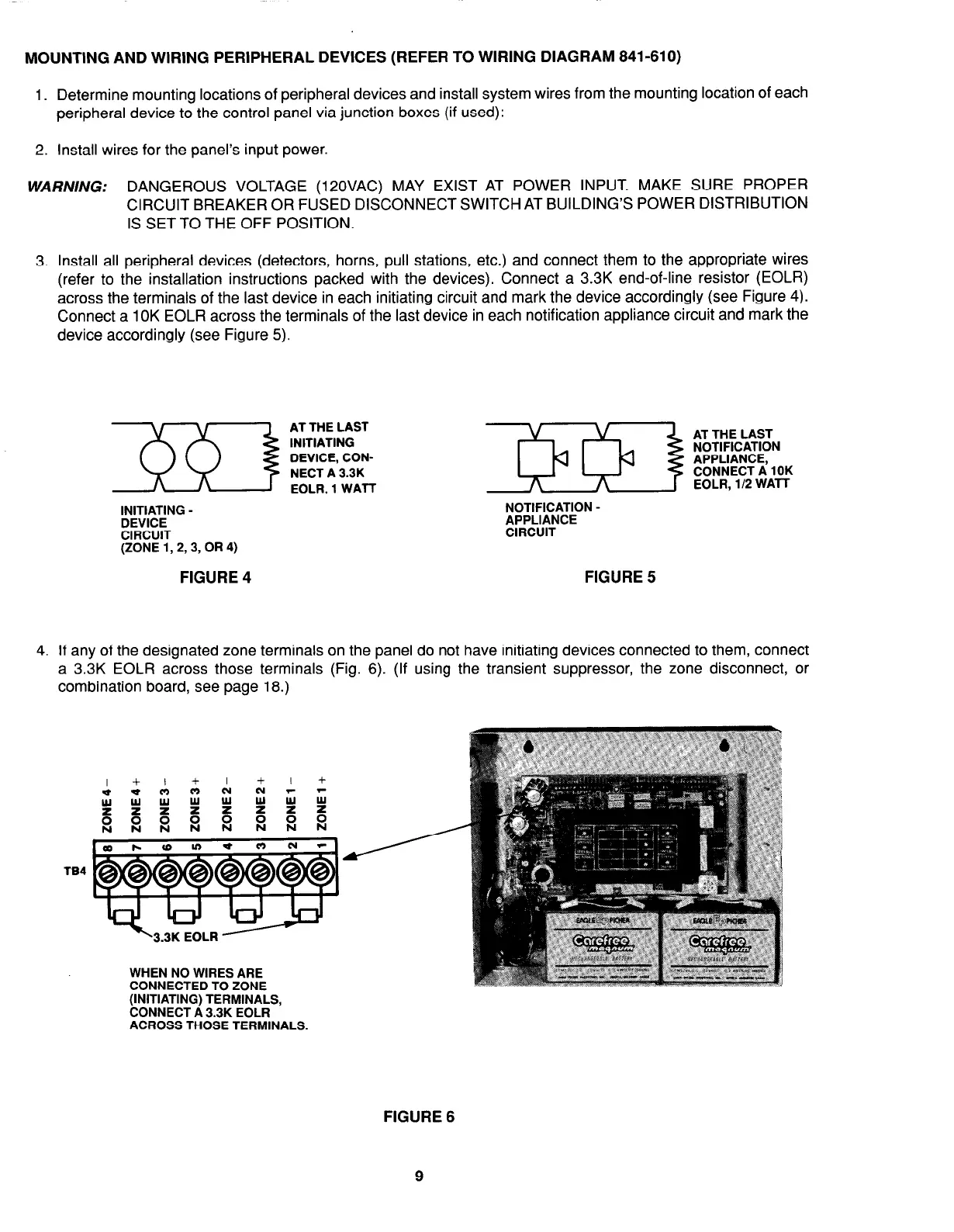
3. Install all peripheral devices (detectors, horns, pull stations, etc.) and connect them to the appropriate wires
(refer to the installation instructions packed with the devices). Connect a 3.3K end-of-line resistor (EOLR)
across the terminals of the last device in each initiating circuit and mark the device accordingly (see Figure 4).
Connect a 1 OK EOLR across the terminals of the last device in each notification appliance circuit and mark the
device accordingly (see Figure 5).
~~&lA&lNG -
CIRCUIT
(ZONE 1,2,3, OR 4)
NOTIFICATION -
tJV’bT;CE
FIGURE 4
FIGURE 5
4. If any of the designated zone terminals on the panel do not have initiating devices connected to them, connect
a 3.3K EOLR across those terminals (Fig. 6). (If using the transient suppressor, the zone disconnect, or
combination board, see page 18.)
TB4
WHEN NO WIRES ARE
CONNECTED TO ZONE
(INITIATING) TERMINALS,
CONNECT A 3.3K EOLR
ACROSS THOSE TERMINALS.
FIGURE 6
9