INSTALLATION INSTRUCTIONS
INTRODUCTION
Be sure that you are thoroughly familiar with this installation procedure before installing the system.
To help you with the installation of this and other Simplex systems, the following publication is available for general
reference: How to Wire a Building for a Fire Alarm System.
TOOLS AND EQUIPMENT REQUIRED
l
l/4-Inch Flat-tip Screwdriver, 8-Inches long
l
l/8-Inch Flat-tip Screwdriver, 4-Inches long
l
Volt-ohmmeter
l
Diagonal Cutting Pliers
0 Wire Strippers
l
End-Of-Line resistors (EOLRs) (supplied by Simplex): five 3.3K, 1 watt resistors; two 1 OK, l/2 watt resistors; two
lK, 1 watt, resistors
l
System Wiring Diagram 841-610.
GENERAL NOTES
l
Notify appropriate personnel (building occupants, fire department or monitoring facility, etc.) of the installation.
l
When running wires to control panel, identify wires appropriately: 12OVAC input power, notification (signal) circuit,
zone 1, zone 2, etc., and identify all ‘I+” wires and ‘I-” wires.
l
The panel’s terminal boards are labeled with a TB number (TBI, TB2, TB3, etc.), and each terminal is designated
a terminal number (1, 2, 3, etc.). Therefore, TBl-1 is terminal 1 on terminal board TBl, TBl-2 is terminal 2 on
terminal board TBl, etc. Each terminal is also identified with an abbreviation of the circuit wire that is to be
connected to it (SIG -, SIG +, ZONl -, ZONl+, etc.).
l
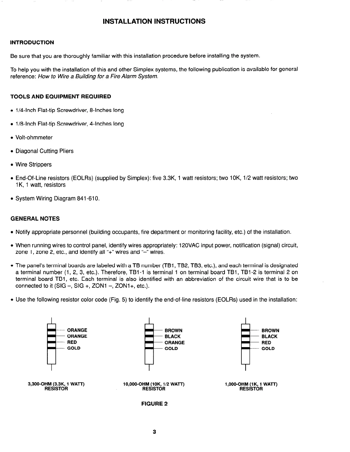
Use the following resistor color code (Fig. 5) to identify the end-of-line resistors (EOLRs) used in the installation:
ORANGE
ORANGE
RED
GOLD
3,300-OHM (3.3K, 1 WAlT)
RESISTOR
BROWN
BLACK
ORANGE
GOLD
lO,OOO-OHM (lOK, l/2 WATT)
RESISTOR
BROWN
BLACK
RED
GOLD
1 ,OOO-OHM (1 K, 1 WAlT)
RESISTOR
FIGURE 2
3