SYSTEM INTRODUCTION - Continued
Alarm-notification appliances are located throughout the building to provide acceptable sound levels. These
appliances are connected to a notification-appliance circuit on the control panel. The control panel activates the
notification appliances from a central location.
You operate the system using the LED indicators and switches on the control panel. When an alarm or trouble
condition exists, the panel LEDs indicate the location and type of condition.
l
Red LEDs indicate an alarm condition when on.
l
Amber LEDs indicate a trouble condition when on.
Switches allow you to interact with the system in various ways (see Operating Instructions on Page 23).
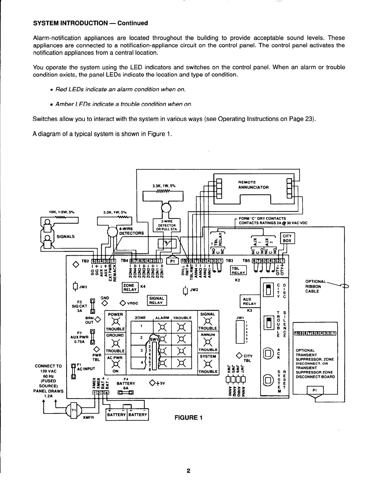
A diagram of a typical system is shown in Figure 1.
3.3K. 1W. 5%
9
ANNUNCIATOR
10K. l/ZW.S%
3.3K. 1W. 5%
- 1
CONTACTS RATINGS ZA.@ 30 VACWDC
CONNECT TO
120 VAC
SOHZ
(FUSED
SOURCE)
PANEL DRAWS
1.2A
9 +
JW3
GND
F3
SIG CKT
-.
BRN
OUT
0
F2
AUX PWR
0.75A
xx
0
PWR
TBL
Fl
AC INPUT
K2
r
JW2
JWl
0
:
3
:
6
,
ITROUBLE I
cc+ 1
r”ztt
F4
BAlTERY
ow
xxmm
WEea
1
FIGURE 1
2
OPTIONAL
RIBBON -
CABLE
OPTIONAL
TRANSIENT
SUPPRESSOR. ZONE
DISCONNECT. OR
TRANSIENT
SUPPRESSOR ZONE
DISCONNECT BOARD
--w
I