TRANSIENT SUPPRESSOR, ZONE DISCONNECT, OR COMBINATION TRANSIENT SUPPRESSOR/ZONE
DISCONNECT BOARD TERMINAL CONNECTIONS (REFER TO WIRING DIAGRAM 841-610 AND FIGURE 22)
Note: Perform Steps 1 through 4 if the system is using the transient suppressor board or combination board.
Perform only Steps 2 through 4 if the system is using the zone disconnect board.
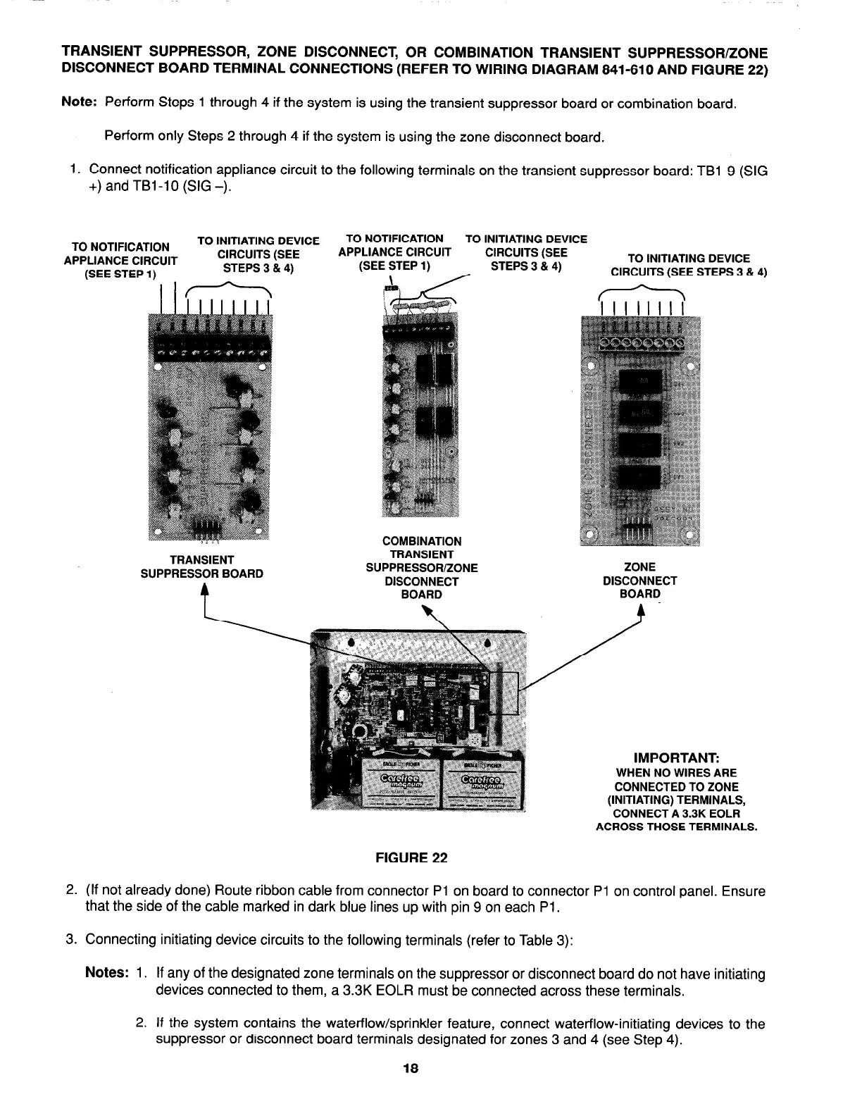
1. Connect notification appliance circuit to the following terminals on the transient suppressor board: TBl-9 (SIG
+) and TBI-10 (SIG -).
TO NOTIFICATION
APPLIANCE CIRCUIT
(SEE STEP 1)
TO INITIATING DEVICE
TO NOTIFICATION
TO INITIATING DEVICE
CIRCUITS (SEE
APPLIANCE CIRCUIT
CIRCUITS (SEE
(SEE STEP 1)
STEPS 3 & 4)
TO INITIATING DEVICE
STEPS 3 814)
I
CIRCUITS (SEE STEPS 3 814)
TRANSIENT
SUPPRESSOR BOARD
COMBINATION
TRANSIENT
SUPPRESSOR/ZONE
DISCONNECT
BOARD
ZONE
DISCONNECT
BOARD
IMPORTANT:
WHEN NO WIRES ARE
CONNECTED TO ZONE
(INITIATING) TERMINALS,
CONNECT A 3.3K EOLR
ACROSS THOSE TERMINALS.
FIGURE 22
2. (If not already done) Route ribbon cable from connector Pl on board to connector Pl on control panel. Ensure
that the side of the cable marked in dark blue lines up with pin 9 on each Pl.
3. Connecting initiating device circuits to the following terminals (refer to Table 3):
Notes: 1. If any of the designated zone terminals on the suppressor or disconnect board do not have initiating
devices connected to them, a 3.3K EOLR must be connected across these terminals.
2.
If the system contains the waterflow/sprinkler feature, connect waterflow-initiating devices to the
suppressor or disconnect board terminals designated for zones
3
and
4
(see Step
4).
18