INSTALLATION PROCEDURES
CONTROL PANEL MOUNTING (Refer to Figure 3)
1. Unlock and open panel door.
2. Unsnap and remove panel overlay from circuit card.
3. Remove knockout plugs on box assembly for wire entry.
4. At control panel mounting location, position control panel and secure with fasteners which are capable of
supporting panel with batteries. Holes are provided at rear of box for securing panel to wall.
5. Enter external wires into control panel.
l
For semi-flush mounting, install trim panel and secure with six screws.
6. If using transient suppressor, zone disconnect, or combination transient suppressor/zone disconnect board,
install board as follows:
a. Secure hex spacers to studs on box assembly.
b. Align board with spacers and secure with four screws.
c. Connect cable to board and control panel as shown (blue edge of cable should line up with pin 9 on each
connector).
7. If using external battery cabinet, mount it using the instruction provided with the cabinet. The battery cabinet
should be close-nippled to the control panel (maximum two feet apart).
8. If using battery meter module or alarm relay module, mount it using the instructions provided with the module.
Make sure the module is within six inches of the control panel.
9. PERFORM THIS STEP ONLY IF PANEL USES ALARM VERIFICATION.
An alarm verification label (P/N 519-532) is provided with the control panel. In the space labeled “CIRCUIT
(ZONE),” indicate the zones for which alarm verification is used. (Refer to Notes 2 and 3 on Page 26.)
In the space labeled “CONTROL UNIT DELAY-SEC,” enter the number “41.”
10. If required by local codes, install the red 4001-9812 peel-and-stick applique on the control panel door using the
instructions provided with the applique.
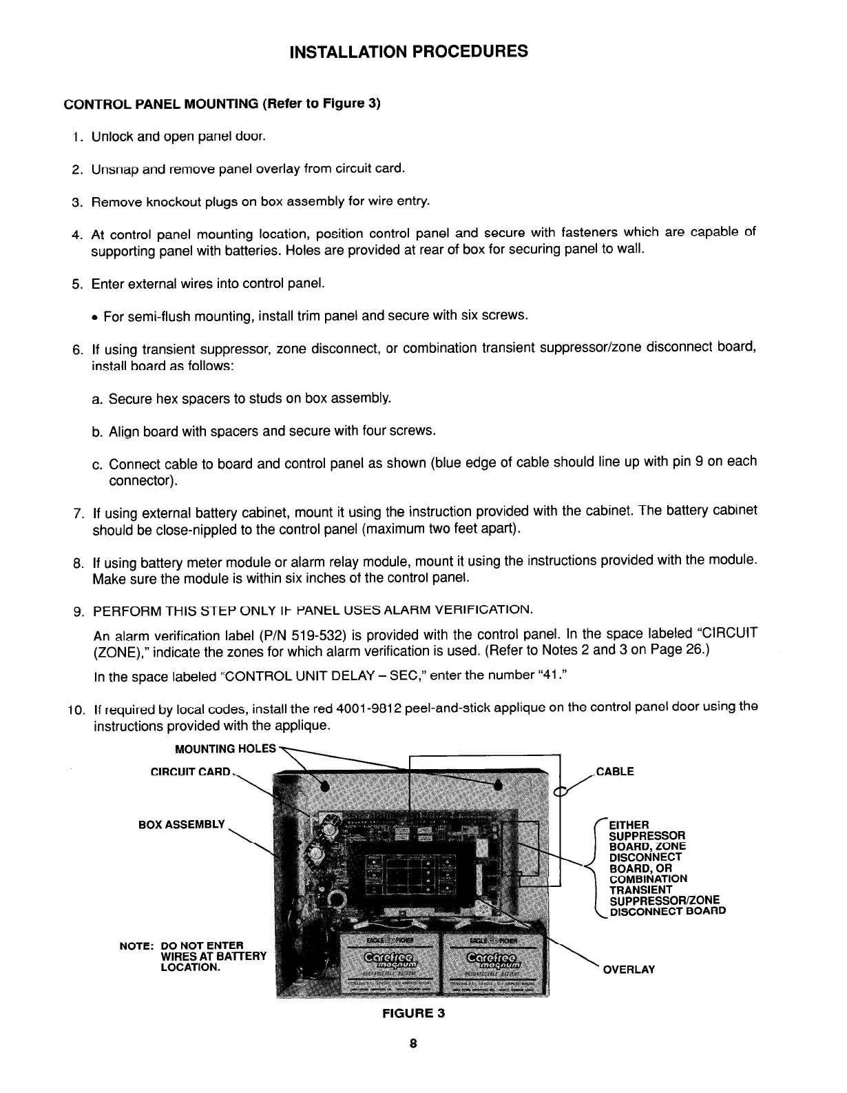
MOUNTING HOLES
CIRCUIT CARD
BOX ASSEMBLY
SUPPRESSOR
SUPPRESSOR/ZONE
DISCONNECT BOARD
NOTE: DO NOT ENTER
WIRES AT BATTERY
LOCATION.
FIGURE 3
8