SYSTEM WIRIING SPECIFICATIONS - Continued
Auxiliary Alarm Relay Contacts (If Used)
Devices - Damper and fan controls, smoke door releases, elevator control, etc.
Source - External 3OVAC/3OVDC @ 2A, dependent upon devices that are used.
Wiring - Two Form C contacts available which transfer upon automatic alarm. Use 18AWG to 14AWG wire.
Trouble Relay Contacts (If Used)
Devices
-
Horns,
bells, lights,
etc.
Source - External 3OVAC/SOVDC dependent upon devices that are used. Max. load is 2A resistive.
Wiring - One Form C contact available which transfers upon a trouble condition. Use 18AWG to 14AWG wire.
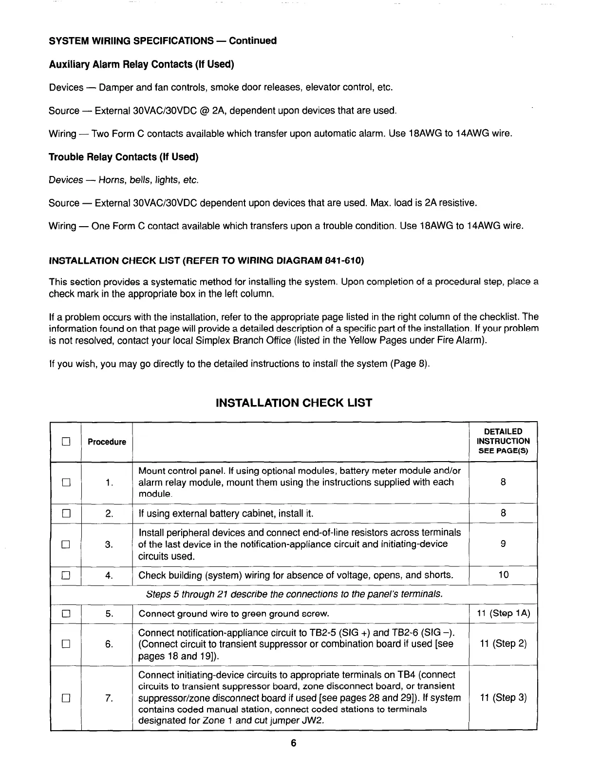
INSTALLATION CHECK LIST (REFER TO WIRING DIAGRAM 841-610)
This section provides a systematic method for installing the system. Upon completion of a procedural step, place a
check mark in the appropriate box in the left column.
If a problem occurs with the installation, refer to the appropriate page listed in the right column of the checklist. The
information found on that page will provide a detailed description of a specific part of the installation. If your problem
is not resolved, contact your local Simplex Branch Office (listed in the Yellow Pages under Fire Alarm).
If you wish, you may go directly to the detailed instructions to install the system (Page 8).
INSTALLATION CHECK LIST
DETAILED
q
Procedure
INSTRUCTION
SEE PAGE(S)
Mount control panel. If using optional modules, battery meter module and/or
q
1. alarm relay module, mount them using the instructions supplied with each
8
module.
q
2. If using external battery cabinet, install it.
8
Install peripheral devices and connect end-of-line resistors across terminals
q
3.
of the last device in the notification-appliance circuit and initiating-device
9
circuits used.
q
4. Check building (system) wiring for absence of voltage, opens, and shorts.
10
Steps 5 through 21 describe the connections to the panel’s terminals.
q
5. Connect ground wire to green ground screw.
11 (Step 1A)
Connect notification-appliance circuit to TB2-5 (SIG +) and TB2-6 (SIG -).
q
6. (Connect circuit to transient suppressor or combination board if used [see
11 (Step 2)
pages 18 and 191).
Connect initiating-device circuits to appropriate terminals on TB4 (connect
circuits to transient suppressor board, zone disconnect board, or transient
q
7. suppressor/zone disconnect board if used [see pages 28 and 291). If system
11 (Step 3)
contains coded manual station, connect coded stations to terminals
designated for Zone 1 and cut jumper JW2.
6