CONTROL PANEL TERMINAL CONNECTIONS - Continued
Notes: 1. If the system contains the transient suppressor board, the zone disconnect board, or the transient
suppressor/zone disconnect board, connect initiating device circuits to the suppressor or disconnect
board instead of the panel terminals (see Page 18).
2. If any of the designated zone terminals do not have alarm devices connected to them, a 3.3K EOLR must
be connected across those terminals (or the appropriate terminals on the suppressor board or zone
disconnect board, if used).
3. If the system contains the waterflow/sprinkler feature, connect waterflow-initiating devices to terminals
designated for zones 3 and 4 (see Page 13).
4. If the system contains coded manual stations, connect stations to zone 1 and cut jumper JW2 (Fig. 12).
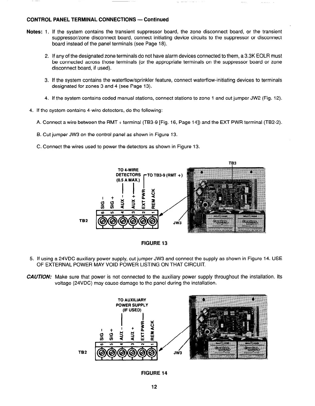
4. If the system contains 4-wire detectors, do the following:
A. Connect a wire between the RMT + terminal (TB3-9 [Fig. 16, Page 141) and the EXT PWR terminal (TB2-2).
B. Cut jumper JW3 on the control panel as shown in Figure 13.
C. Connect the wires used to power the detectors as shown in Figure 13.
TB3
TB2
FIGURE 13
5. If using a 24VDC auxiliary power supply, cut jumper JW3 and connect the supply as shown in Figure 14. USE
OF EXTERNAL POWER MAY VOID POWER LISTING ON THAT CIRCUIT.
CAUTION: Make sure that power is not connected to the auxiliary power supply throughout the installation. Its
voltage (24VDC) may cause damage to the panel during the installation.
TB2
FIGURE 14
12