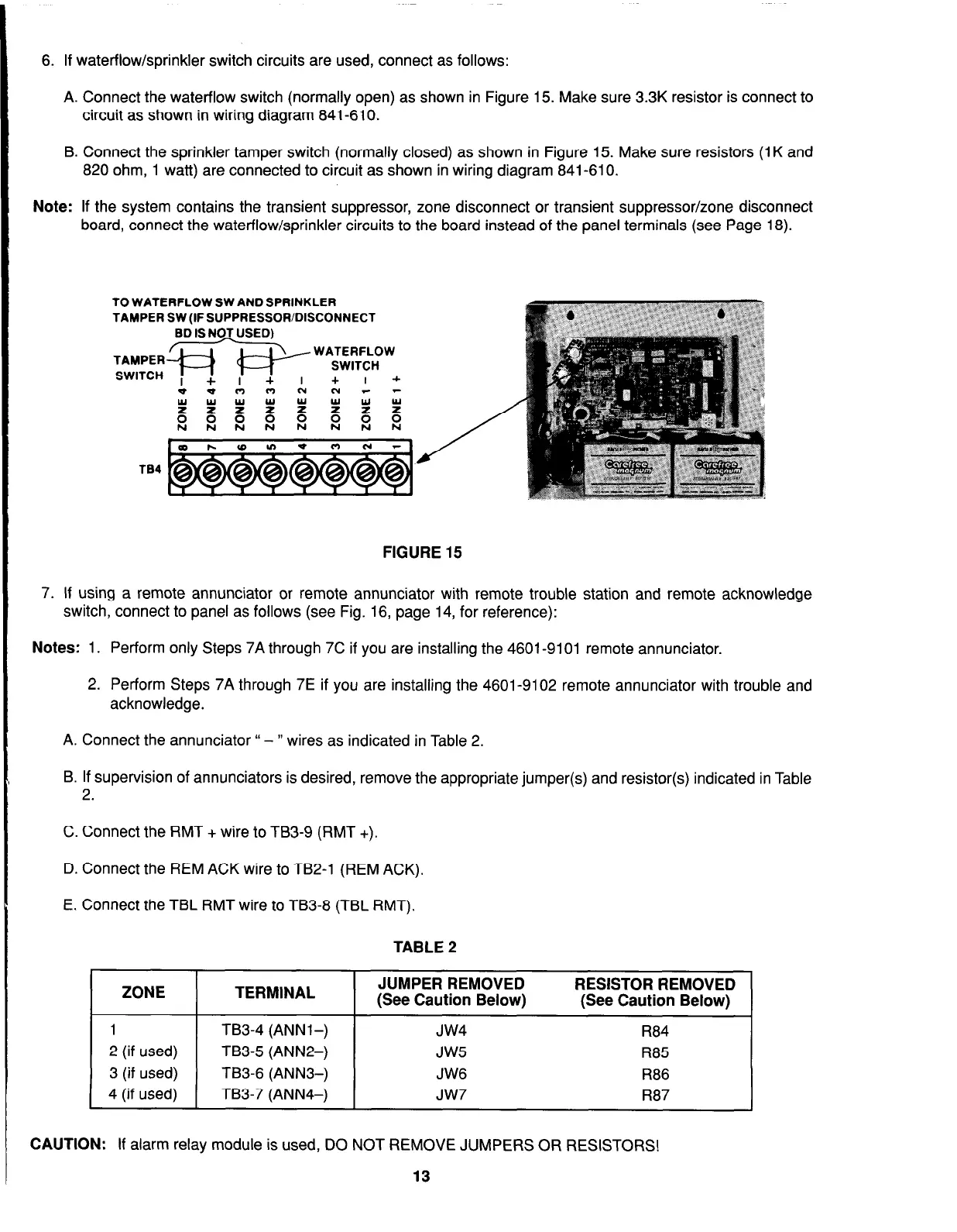
6. If waterflow/sprinkler switch circuits are used, connect as follows:
A. Connect the waterflow switch (normally open) as shown in Figure 15. Make sure 3.3K resistor is connect to
circuit as shown in wiring diagram 841-610.
B. Connect the sprinkler tamper switch (normally closed) as shown in Figure 15. Make sure resistors (1 K and
820 ohm, 1 watt) are connected to circuit as shown in wiring diagram 841-610.
Note: If the system contains the transient suppressor, zone disconnect or transient suppressor/zone disconnect
board, connect the waterflow/sprinkler circuits to the board instead of the panel terminals (see Page 18).
TO WATERFLOW SW AND SPRINKLER
TAMPER SW (IF SUPPRESSOR/DISCONNECT
ED IS NO_T USED)
FIGURE 15
7. If using a remote annunciator or remote annunciator with remote trouble station and remote acknowledge
switch, connect to panel as follows (see Fig. 16, page 14, for reference):
Notes: 1. Perform only Steps 7A through 7C if you are installing the 4601-9101 remote annunciator.
2. Perform Steps 7A through 7E if you are installing the 4601-9102 remote annunciator with trouble and
acknowledge.
A. Connect the annunciator “ - ” wires as indicated in Table 2.
B. If supervision of annunciators is desired, remove the appropriate jumper(s) and resistor(s) indicated in Table
2.
C. Connect the RMT + wire to TB3-9 (RMT +).
D. Connect the REM ACK wire to TB2-1 (REM ACK).
E. Connect the TBL RMT wire to TB3-8 (TBL RMT).
TABLE 2
I
ZONE
I
TERMINAL
I
JUMPER REMOVED
RESISTOR REMOVED
(See Caution Below)
(See Caution Below)
I
1
TB3-4 (ANNl-)
JW4
R84
2 (if used) TB3-5 (ANN2-)
JW5
R85
3 (if used) TB3-6 (ANNS-)
JW6
R86
4 (if used) TB3-7 (ANN4-)
JW7
R87
CAUTION: If alarm relay module is used, DO NOT REMOVE JUMPERS OR RESISTORS!
13