CONTROL PANEL TERMINAL CONNECTIONS - Continued
162
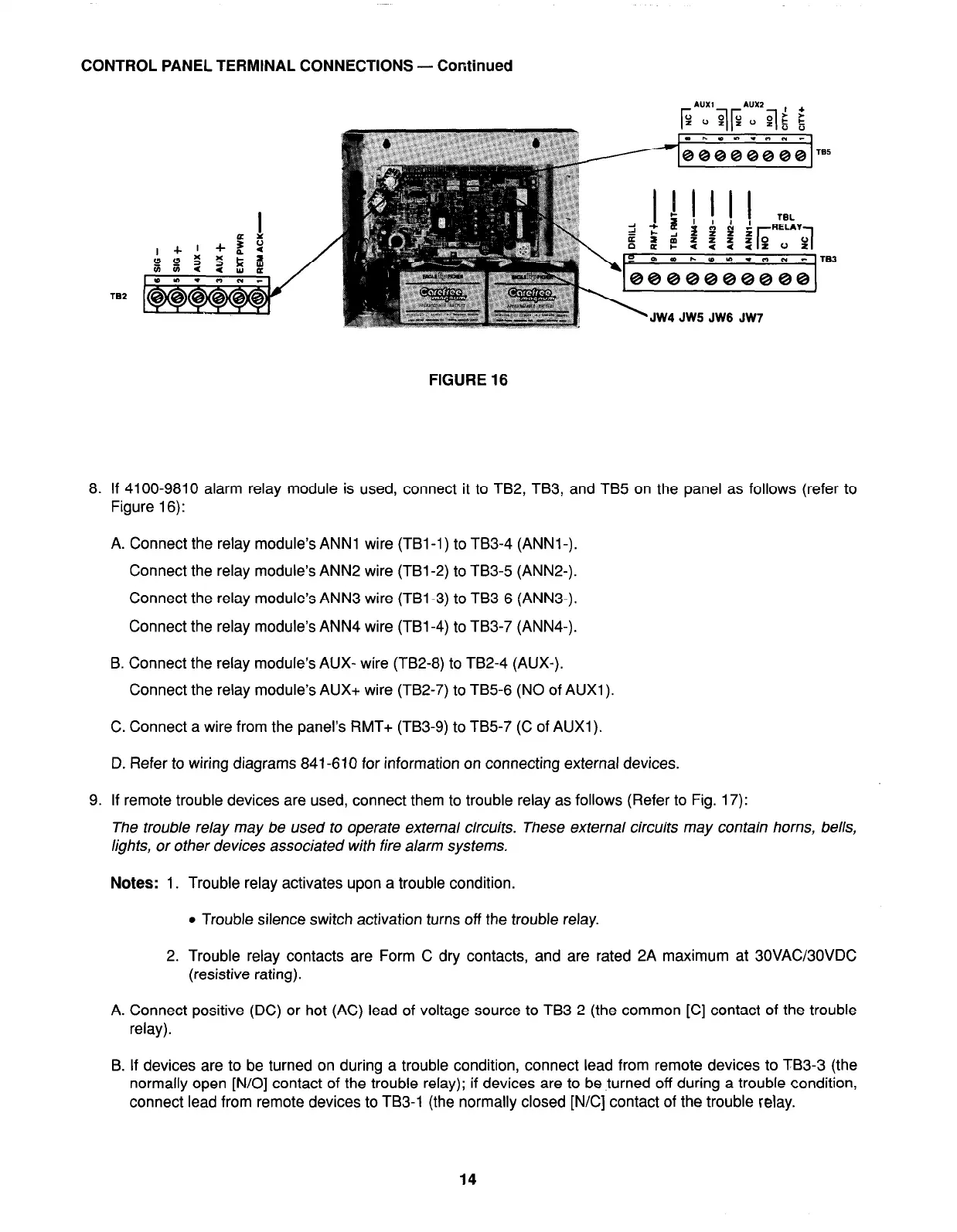
JW4 JW5 JW6 JW7
FIGURE 16
8. If 4100-9810 alarm relay module is used, connect it to TB2, TB3, and TB5 on the panel as follows (refer to
Figure 16):
A. Connect the relay module’s ANN1 wire (TBl-1) to TB3-4 (ANNl-).
Connect the relay module’s ANN2 wire (TBl-2) to TB3-5 (ANN2-).
Connect the relay module’s ANN3 wire (TBl-3) to TB3-6 (ANN3-).
Connect the relay module’s ANN4 wire (TBl-4) to TB3-7 (ANN4-).
B. Connect the relay module’s AUX- wire (TB2-8) to TB2-4 (AUX-).
Connect the relay module’s AUX+ wire (TB2-7) to TB5-6 (NO of AUXl).
C. Connect a wire from the panel’s RMT+ (TB3-9) to TB5-7 (C of AUXl).
D. Refer to wiring diagrams 841-610 for information on connecting external devices.
9. If remote trouble devices are used, connect them to trouble relay as follows (Refer to Fig. 17):
The trouble relay may be used to operate external circuits. These external circuits may contain horns, bells,
lights, or other devices associated with fire alarm systems.
Notes: 1. Trouble relay activates upon a trouble condition.
l
Trouble silence switch activation turns off the trouble relay.
2. Trouble relay contacts are Form C dry contacts, and are rated 2A maximum at 30VACMOVDC
(resistive rating).
A. Connect positive (DC) or hot (AC) lead of voltage source to TB3-2 (the common [C] contact of the trouble
relay).
B. If devices are to be turned on during a trouble condition, connect lead from remote devices to TB3-3 (the
normally open [N/O] contact of the trouble relay); if devices are to be turned off during a trouble condition,
connect lead from remote devices to TB3-1 (the normally closed [N/C] contact of the trouble relay.
14