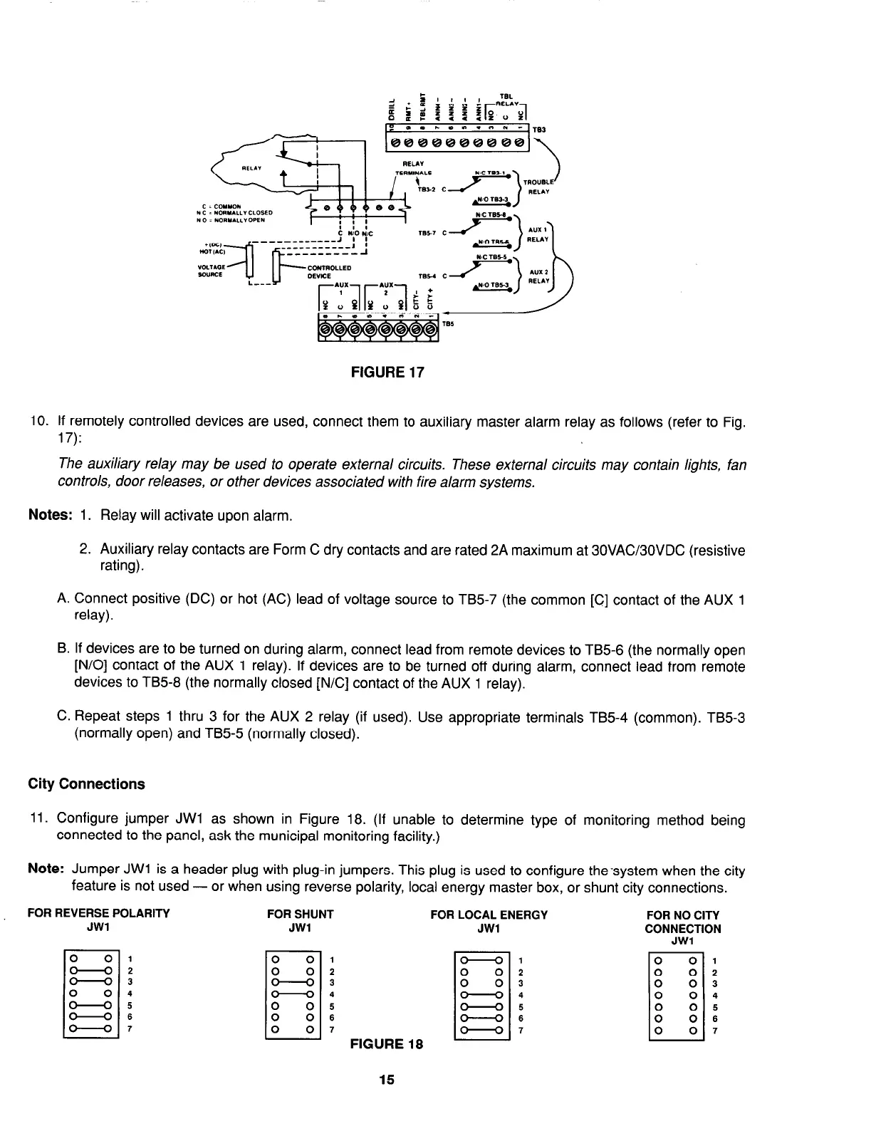
FIGURE 17
10. If remotely controlled devices are used, connect them to auxiliary master alarm relay as follows (refer to Fig.
17):
The auxiliary relay may be used to operate external circuits. These external circuits may contain lights, fan
controls, door releases, or other devices associated with fire alarm systems.
Notes: 1. Relay will activate upon alarm.
2. Auxiliary relay contacts are Form C dry contacts and are rated 2A maximum at 30VAC30VDC (resistive
rating).
A. Connect positive (DC) or hot (AC) lead of voltage source to TB5-7 (the common [C] contact of the AUX 1
relay).
B. If devices are to be turned on during alarm, connect lead from remote devices to TB5-6 (the normally open
[N/O] contact of the AUX 1 relay). If devices are to be turned off during alarm, connect lead from remote
devices to TB5-8 (the normally closed [N/C] contact of the AUX 1 relay).
C. Repeat steps 1 thru 3 for the AUX 2 relay (if used). Use appropriate terminals TB5-4 (common). TB5-3
(normally open) and TB5-5 (normally closed).
City Connections
11. Configure jumper JWl as shown in Figure 18. (If unable to determine type of monitoring method being
connected to the panel, ask the municipal monitoring facility.)
Note: Jumper JWl is a header plug with plug-in jumpers. This plug is used to configure the-system when the city
feature is not used - or when using reverse polarity, local energy master box, or shunt city connections.
FOR REVERSE POLARITY
FOR SHUNT
FOR LOCAL ENERGY
FOR NO CITY
JWl JWl
CONNECTION
JWl
0
0
1
0
0 2
-3
7
-4
0
0 5
0
0
6
0
0 7
FIGURE 18
0
: 0
z
0
01
0
0 2
0
0 3
7
0
0 4
0
0 5
0 0
6
0
0 7
15