CONTROL PANEL TERMINAL CONNECTIONS - Continued
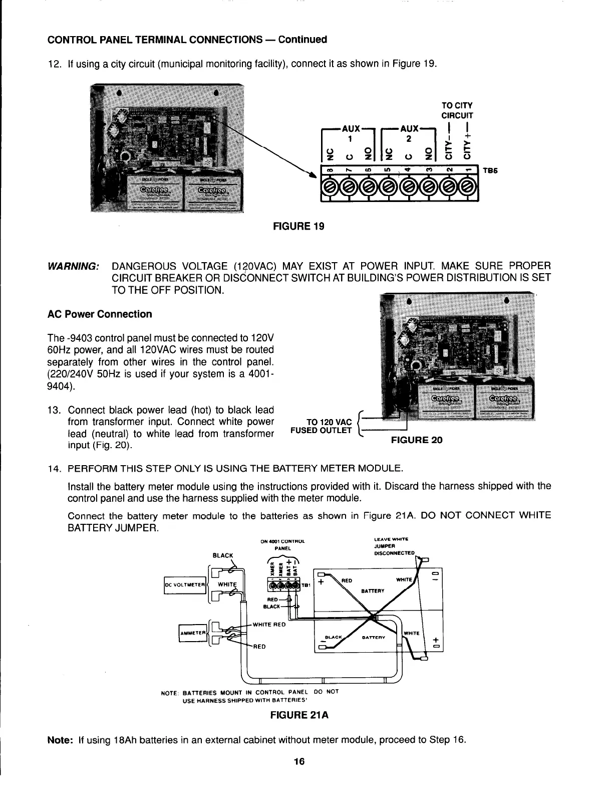
12. If using a city circuit (municipal monitoring facility), connect it as shown in Figure 19.
FIGURE 19
WARNING:
DANGEROUS VOLTAGE (1TOVAC) MAY EXIST AT POWER INPUT. MAKE SURE PROPER
CIRCUIT BREAKER OR DISCONNECT SWITCH AT BUILDING’S POWER DISTRIBUTION IS SET
TO THE OFF POSITION.
AC Power Connection
The -9403 control panel must be connected to 12OV
60Hz power, and all 120VAC wires must be routed
separately from other wires in the control panel.
(220/24OV 50Hz is used if your system is a 4001-
9404).
13. Connect black power lead (hot) to black lead
from transformer input. Connect white power
TO 120 VAC
lead (neutral) to white lead from transformer
FUSED OUTLET
input (Fig. 20).
14. PERFORM THIS STEP ONLY IS USING THE BATTERY METER MODULE
Install the battery meter module using the instructions provided with it. Discard the harness shipped with the
control panel and use the harness supplied with the meter module.
Connect the battery meter module to the batteries as shown in Figure 21A. DO NOT
BATTERY JUMPER.
ON ox CONTROL
LEA”E WHlTE
CONNECT WHITE
BLACK
--
II
NOTE BATTERIES MOVNT IN CONTROL PANEL DO NOT
USE HARNESS SHIPPED WITH BATTERIES’
FIGURE 21A
Note: If using 18Ah batteries in an external cabinet without meter module, proceed to Step 16.
16