18
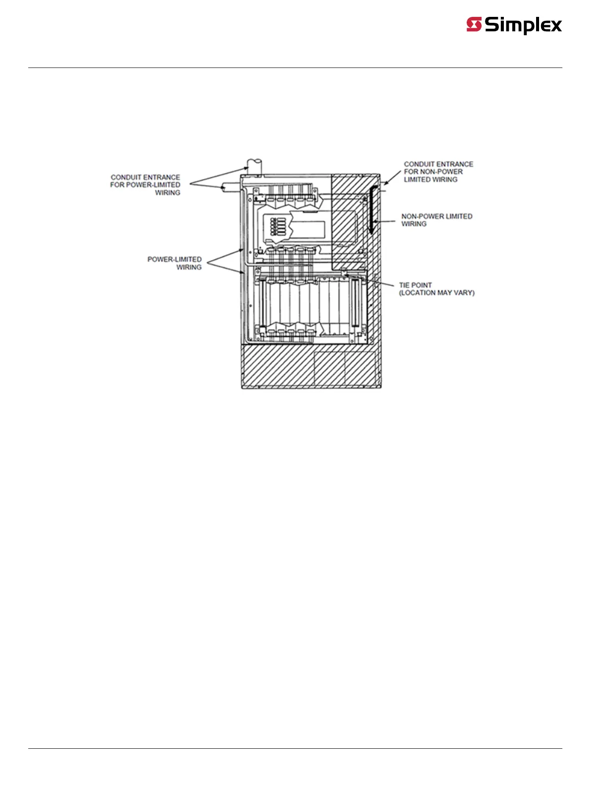
This section contains guidelines and instructions for wiring the relay modules.
Make sure these guidelines are accounted for before wiring:
• All wires must be 18 AWG, twisted/shielded pair.
• All wiring is supervised.
• Conductors must test free of all grounds.
• Power must come from a Simplex-approved power supply.
• All wiring must be done using copper conductors only, unless noted otherwise.
• If shielded wire is used,
- the metallic continuity of the shield must be maintained throughout the entire cable
length.
- the entire length of the cable must have a resistance greater than 1 Megohm to earth
ground.
• Underground wiring must be free of all water.
• In areas of high lightning activity, or in areas that have large power surges, the
2081-9027 Transient Suppressor should be used on monitor points.
• Wires must not be run through elevator shafts.
• Wires that run in plenum must be in conduit.
• Splicing is permitted. All spliced connections must either be soldered (resin-core solder),
crimped in metal sleeves, or encapsulated with an epoxy resin. When soldering or
crimped metal sleeves are used, the junction must be insulated with a high-grade
electrical tape that is as sound as the original insulating jacket. Shield continuity must be
maintained throughout.
• A system ground must be provided for earth detection and lightning protection devices.
This connection must comply with approved earth detection per NFPA780.
• Only system wiring can be run together in the same conduit.
• Any wiring leaving the building requires overload protectors (2081-9044). Use one
overvoltage protector where wiring leaves the building and another where the wiring enters
the other building.
Continued on next page
Wiring
Introduction
General Guidelines