2-12
FigureTag FD4-709-05
+
-
+
-
BACKUP 2
PRIMARY 1
LISTED
SIMPLEX
FIRE ALARM
CONTROL
PANEL
2120,
4001, 4002
4020, 4100+, 4100U,
4100ES, 4004, 4005 OR
4006
BLK
SEE NOTE 4
SEE NOTE 4
SEE
NOTE
3
SEE NOTE 3
EOL
RESISTOR
(IF USED)
BLU
GRY
YEL
ORN
GRN
N/C
C
N/O
N/C
C
N/O
BLK
RED
VIO
(SEE NOTE 5)
(SEE NOTE 2)
BLK RED
REMOTE LED
4098-9830
(SEE NOTE 1)
2
1
3
4
INITIATING
CIRCUIT
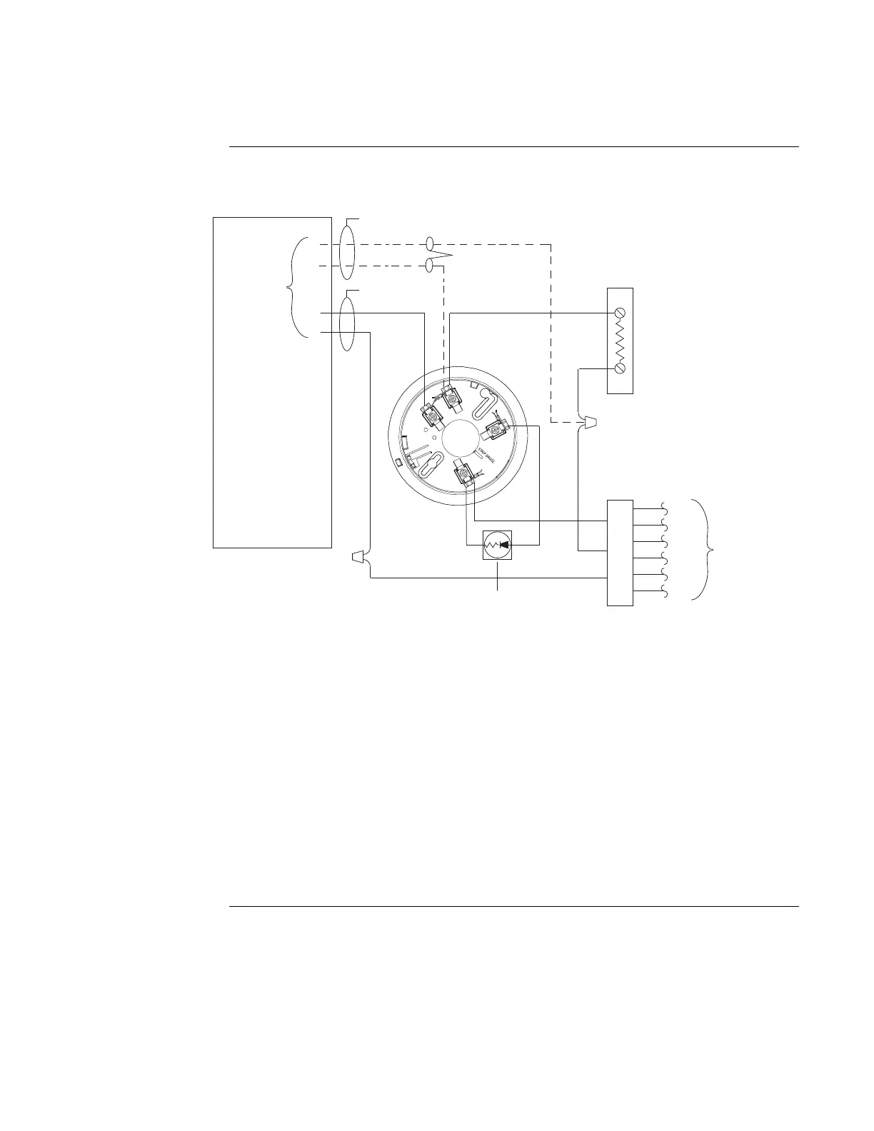
Figure 2-4. 4098-9683 2-Wire Relay Base Connections for Style B or D Initiating Circuits
Notes:
1. If used, 4098-9830 remote LED is polarized; refer to Figure 2-6 to wire remote LED to a heat
detector, observe color-coded wiring.
2. Wire only one relay base per initiating circuit.
3. For Style D initiating circuit, wire per dotted lines and do not use EOL resistor. If Style B
initiating circuit, refer to wiring diagrams provided with the system panel for proper EOL
resistor value.
4. It is recommended that the Primary-1 and the Backup-2 lines be in separate wire runs and in
compliance with local requirements.
5. Aux. Relay contacts, each rated 1 amp at 28 VDC/0.5 amp at 125 VAC, resistive.
Continued on next page
4098 Bases,
Continued
Wiring