2-13
FigureTag FD4-709-06
+
-
LISTED
SIMPLEX
FIRE ALARM
CONTROL
PANEL
2120,
4001, 4002
4020, 4100+, 4100U
4004, 4005 OR 4006
RED RED
BLK
BLK
RED
ORG ORG
BLK BLK
N/C
N/O
VIO
BLU
GRY
GRN GRN
SEE
NOTE
6
SEE
NOTE
6
ORG ORG
BLK BLK
N/C
N/O
VIO
BLU
GRY
GRN GRN
RELAY RELAY
ORG ORG
BLK BLK
N/C
N/O
VIO
BLU
GRY
GRN GRN
RELAY
INITIATING
CIRCUIT
RED RED
BLK
YEL
YEL
RED
24VDC
EOL RELAY
2098-9735
OR
2098-9739
RESETABLE
POWER
SOURCE
24VDC
REMOTE LED
4098-9830
(SEE NOTE 1)
EOL
RESISTOR
(SEE NOTE 3)
REMOTE LED
4098-9830
(SEE NOTE 1)
SEE
NOTE
6
+
-
4100ES ,
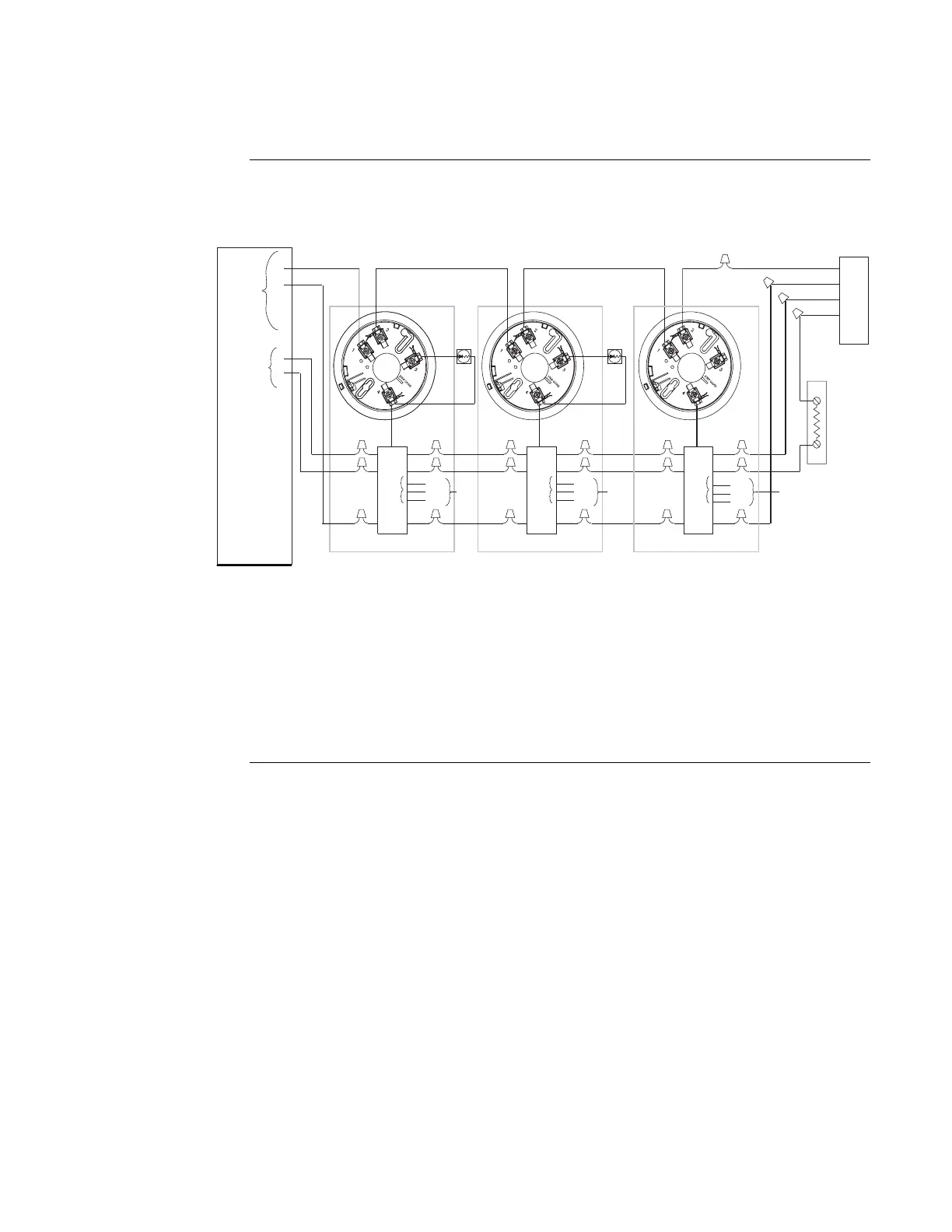
Figure 2-5. 4098-9682 4-Wire Base Connections for Style B Initiating Circuits
Notes:
1. If used, 4098-9830 remote LED is polarized, observe color-coded wiring.
(Refer to Figure 2-6 to wire remote LED to heat detector.)
2. Aux. Alarm contacts - Form C - each rated 3 amps at 28 VDC/115 VAC, resistive.
3. Refer to wiring diagrams provided with system panel for proper EOL resistor value.
Continued on next page
4098 Bases,
Continued
Wiring