Setting DIP switches on WWV Interface Board
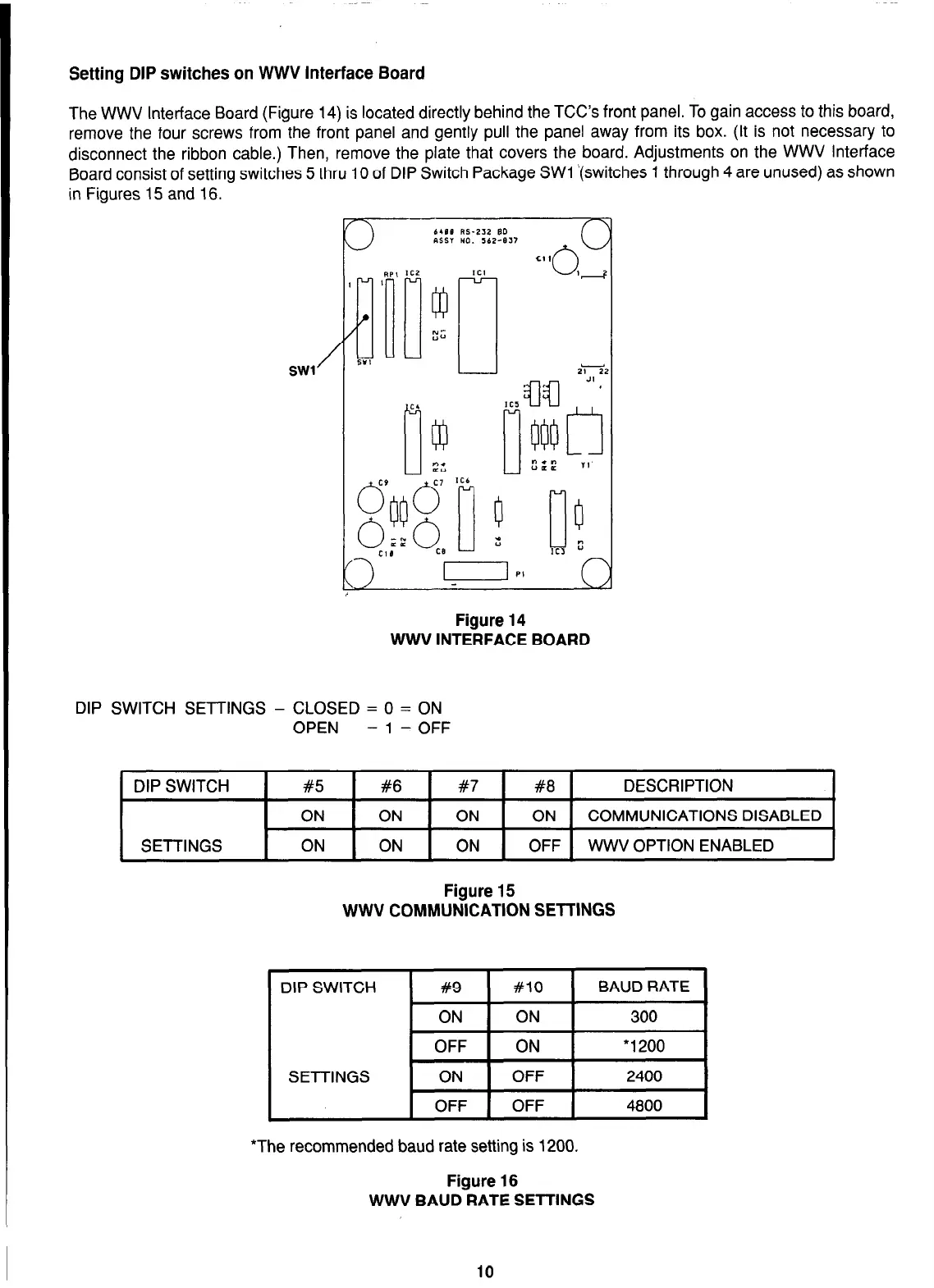
The WWV Interface Board (Figure 14) is located directly behind the TCC’s front panel. To gain access to this board,
remove the four screws from the front panel and gently pull the panel away from its box. (It is not necessary to
disconnect the ribbon cable.) Then, remove the plate that covers the board. Adjustments on the WWV Interface
Board consist of setting switches 5 thru 10 of DIP Switch Package SW1 ‘(switches 1 through 4 are unused) as shown
in Figures 15 and 16. -
Figure 14
WWV INTERFACE BOARD
DIP SWITCH SETTINGS - CLOSED = 0 = ON
OPEN = 1 = OFF
DIP SWITCH
!
#5 1 #6 1 #7 1 #8 1 DESCRIPTION
I
ON ON ON ON COMMUNICATIONS DISABLED
SETTINGS ON ON ON OFF WWV OPTION ENABLED
Figure 15
WWV COMMUNICATION SETTINGS
DIP SWITCH
SETTINGS
#9 #lO
BAUD RATE
ON ON 300
OFF ON *1200
ON OFF 2400
OFF OFF
4800
*The recommended baud rate setting is 1200.
Figure 16
WWV BAUD RATE SETTINGS
10