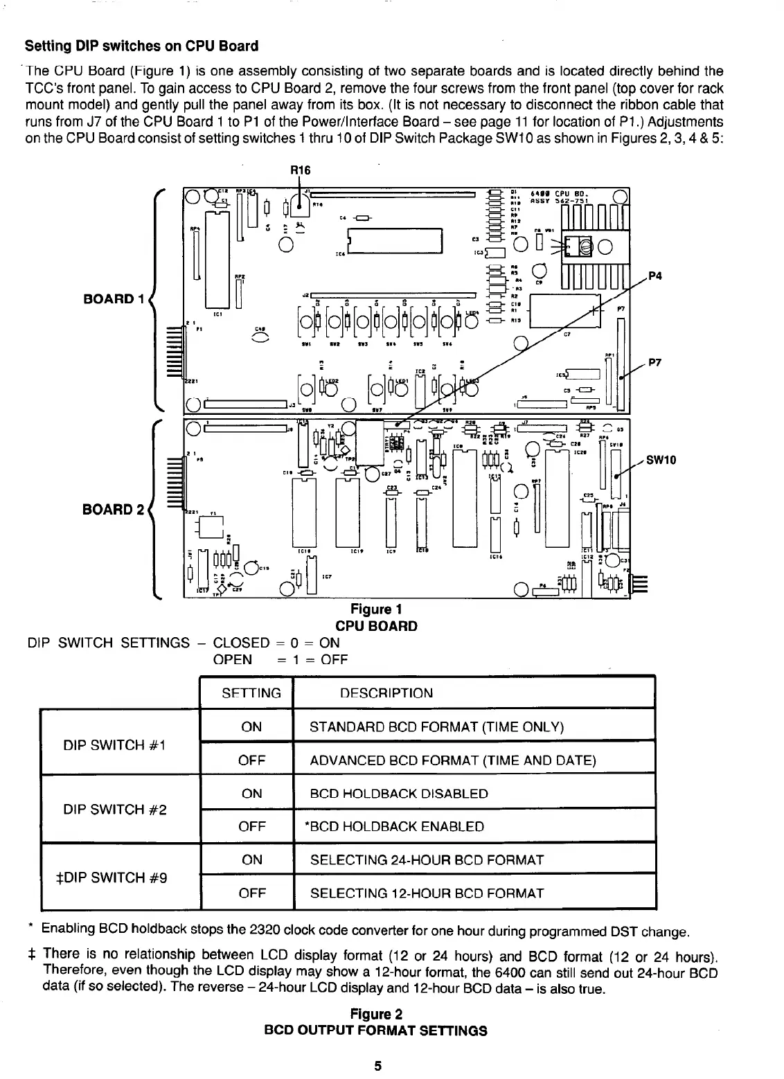
Setting DIP switches on CPU Board
The CPU Board (Figure 1) is one assembly consisting of two separate boards and is located directly behind the
TCC’s front panel. To gain access to CPU Board 2, remove the four screws from the front panel (top cover for rack
mount model) and gently pull the panel away from its box. (It is not necessary to disconnect the ribbon cable that
runs from J7 of the CPU Board 1 to Pl of the Power/Interface Board -see page 11 for location of Pl.) Adjustments
on the CPU Board consist of setting switches 1 thru 10 of DIP Switch Package SW10 as shown in Figures 2,3,4 & 5:
BOARD 1
BOARD 2
R16
/p4
/ p7
Figure 1
CPU BOARD
DIP SWITCH SETTINGS - CLOSED = 0 = ON
OPEN = 1 = OFF
DIP SWITCH #l
DIP SWITCH #2
SETTING DESCRIPTION
ON STANDARD BCD FORMAT (TIME ONLY)
OFF ADVANCED BCD FORMAT (TIME AND DATE)
ON BCD HOLDBACK DISABLED
OFF
l
BCD HOLDBACK ENABLED
*DIP SWITCH #9
ON SELECTING 24-HOUR BCD FORMAT
OFF SELECTING 12-HOUR BCD FORMAT
* Enabling BCD holdback stops the 2320 clock code converter for one hour during programmed DST change.
$ There is no relationship between LCD display format (12 or 24 hours) and BCD format (12 or 24 hours).
Therefore, even though the LCD display may show a 12-hour format, the 6400 can still send out 24-hour BCD
data (if so selected). The reverse - 24-hour LCD display and 12-hour BCD data - is also true.
Figure 2
BCD OUTPUT FORMAT SETTINGS
5