APPENDIX A
GENERAL MOUNTING INSTRUCTIONS
CAUTION
TO AVOID DAMAGING TCC PC BOARDS, NEVER
PLUG OR UNPLUG PC BOARD CONNECTORS
WITH AC POWER ON.
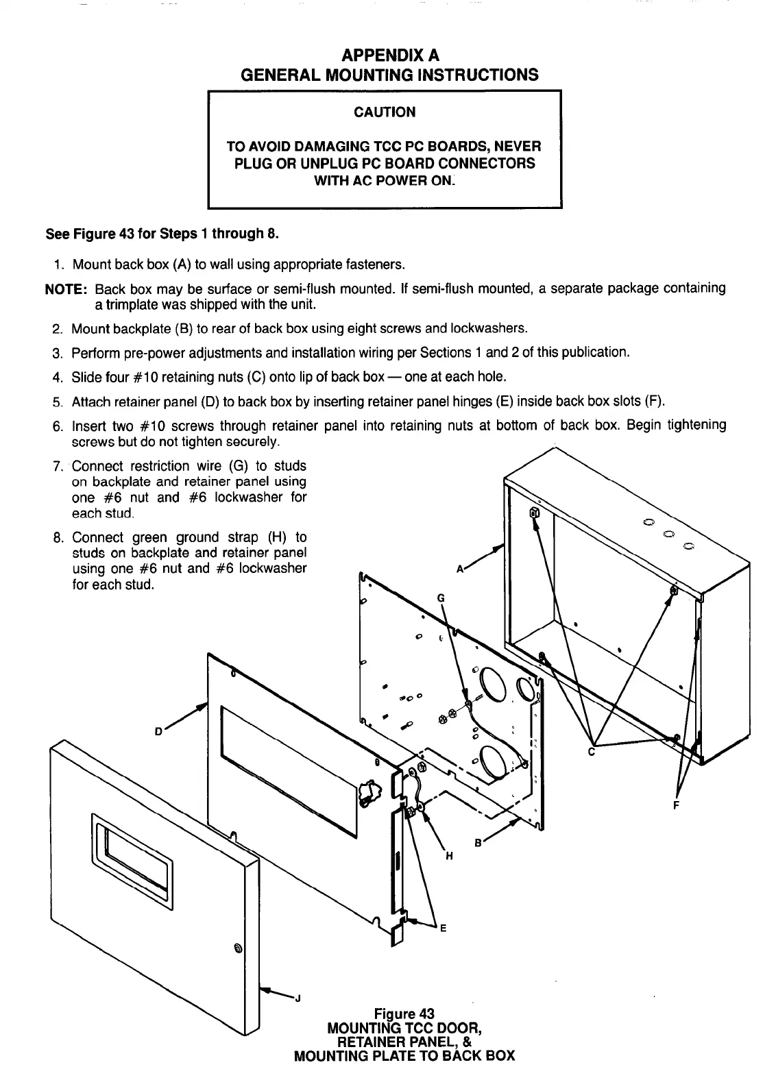
See Figure 43 for Steps 1 through 8.
1.
Mount back box (A) to wall using appropriate fasteners.
NOTE:
Back box may be surface or semi-flush mounted. If semi-flush mounted, a separate package containing
a trimplate was shipped with the unit.
2. Mount backplate (B) to rear of back box using eight screws and lockwashers.
3. Perform pre-power adjustments and installation wiring per Sections 1 and 2 of this publication.
4. Slide four #lO retaining nuts (C) onto lip of back box - one at each hole.
5. Attach retainer panel (D) to back box by inserting retainer panel hinges (E) inside back box slots (F).
6. Insert two #lO screws through retainer panel into retaining nuts at bottom of back box. Begin tightening
screws but do not tighten securely.
7. Connect restriction wire (G) to studs
on backplate and retainer panel using
one #6 nut and #6 lockwasher for
each stud.
8. Connect green ground strap (H) to
studs on backplate and retainer panel
using one #6 nut and #6 lockwasher
for each stud.
-J
Figure 43
MOUNTING TCC DOOR,
RETAINER PANEL, &
MOUNTING PLATE TO BACK BOX
34