11 - 3
11 Drive Controls Service
Parking Brake System Service
GENERAL INFORMATION
The braking system and ground speed control system
are both linked through the lock plate bracket (B, Figure
3) and pivot plate (O). These two parts disengage the
cruise mechanism and lock the parking brake. Locking
either mechanism triggers the parking brake / cruise
switch (B, Figure 1) and illuminates the indicator light in
the dashboard.
PARKING BRAKE LOCK MECHANISM
To lock the parking brake, first the brake pedal is
depressed, rotating the pivot plate (O, Figure 3) and
brake lever (P) past the locking plate bracket (B) (clock-
wise from top). Second the parking brake/cruise knob is
pulled up, rotating the locking plate (B) (clockwise from
top) so that the cruise release tabs (A, Figure 2) move
past each other. At this point, letting up on the brake
pedal allows the cruise release tabs to contact each
other back to back, locking the pivot plate (O, Figure 3)
and bracket lever (P) in the engaged position.
Depressing the brake pedal gives the cruise lock tabs (A,
Figure 2) enough clearance to rotate past each other,
and allows the parking brake knob to be depressed, dis-
engaging the parking brake.
R
A
Q
C
P
O
B
D
E
M
K
N
L
/J
I
G
H
F
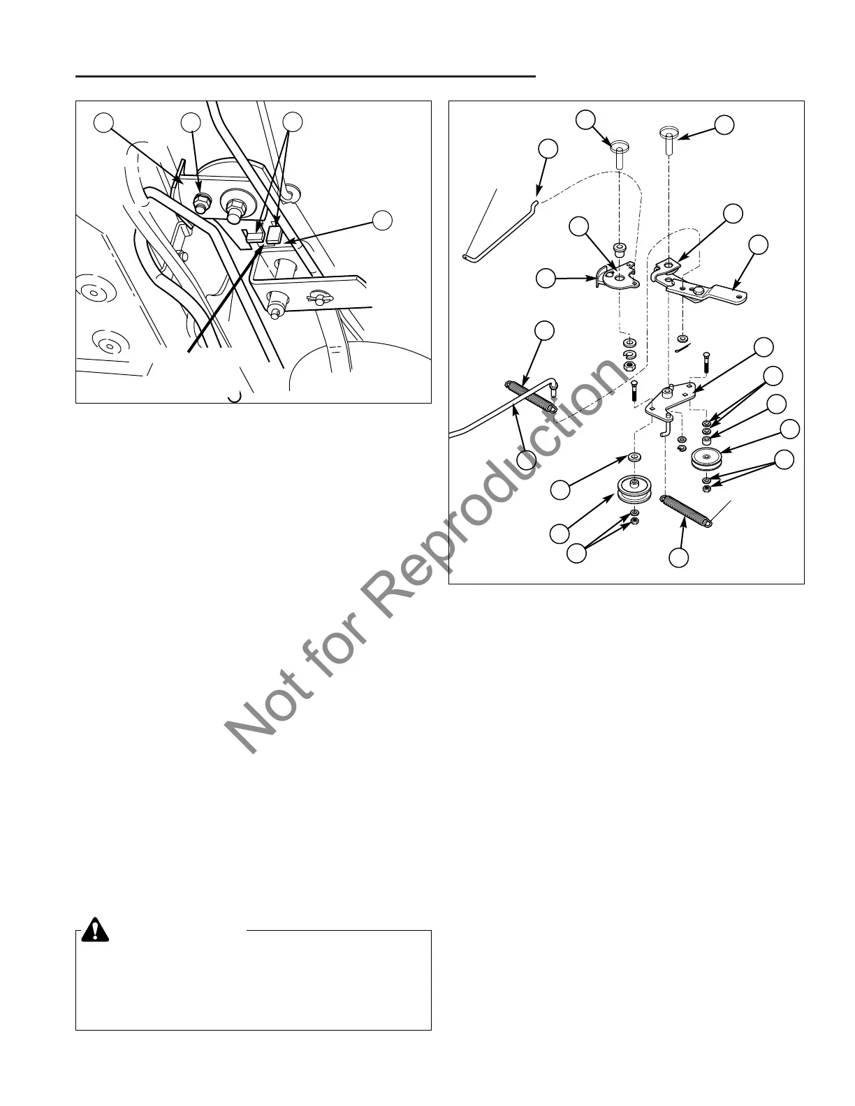
Figure 3. Idler Assembly Detail
A. Cruise Pivot (Frame) J. Washer & Nut
B. Lock Plate Bracket K. V-Idler Pulley
C. Cruise Rod L. Spacer
D. Brake Pedal Spring M. Washers, 3/8
E. Clutch Rod N. Idler Plate
F. Washer, 3/8 Plain O. Pivot Plate
G. Backside Idler Pulley P. Brake Lever
H. Washer & Nut Q. Plate & Pad Assy.
I. Idler Assembly Spring R. Idler Pivot (Frame)
Figure 2. Cruise Control Release Tabs
A. Cruise Release Tabs C. Cruise Lock Cam
B. Brake Cam D. Cam Adj. Bolt
A
B
C
D
NOTE: Idler
Assembly
Removed for
Illustration
Purposes.
1/8” to 3/16”
Gap
BRAKE COMPONENT REPLACEMENT
Rear Brake Rod Replacement
1. Disconnect the brake return spring (L, Figure 1) from
the rear frame bolt.
2. Remove the cotter pin and washer securing the rear of
the rod to the brake arm extension (K).
3. Remove the nut and spacer securing the brake rod
guide to the brake lever (I).
4. Remove the nut and brake spring from the rod, and
replace the rod.
5. Install in reverse order of removal. Be sure to perform
the brake spring adjustment found in Section 4
ADJUSTMENTS.
WARNING
Before beginning any service work, turn the PTO
off, set the parking brake, turn the ignition switch
off, remove the key, disconnect the spark plug
wires, and disconnect the negative battery cable.