R
A
Q
C
P
O
B
D
E
M
K
N
L
/J
I
G
H
F
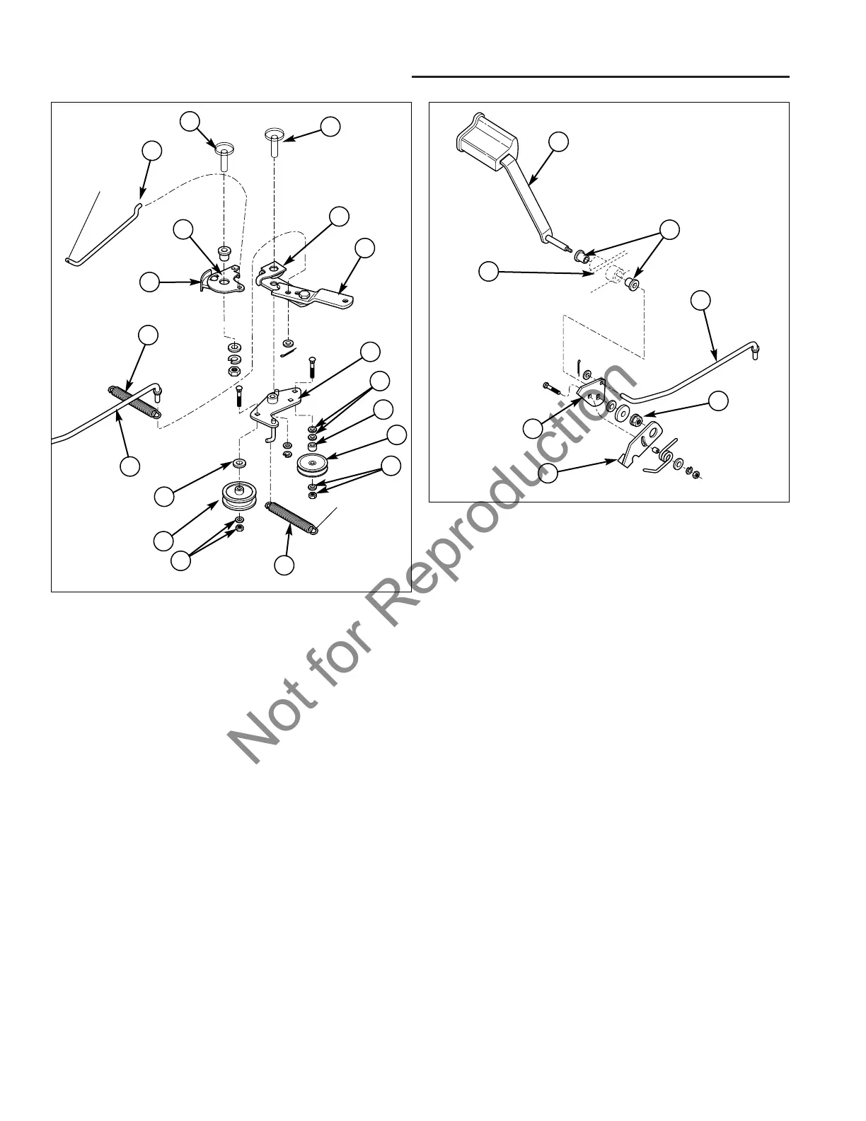
Figure 4. Idler Assembly Detail
A. Cruise Pivot (Frame) J. Washer & Nut
B. Lock Plate Bracket K. V-Idler Pulley
C. Cruise Rod L. Spacer
D. Brake Pedal Spring M. Washer, 3/8
E. Clutch Rod N. Idler Plate
F. Washer, 3/8 Plain O. Pivot Plate
G. Backside Idler Pulley P. Brake Lever
H. Washer & Nut Q. Plate & Pad Assy.
I. Idler Assembly Spring R. Idler Pivot (Frame)
Idler Assembly Service
The idler assembly (N, Figure 4) is not attached to the
brake lever (P). The idler assembly is rotated by contact
between the pivot plate (O) and the stud on the top the
idler plate (N) next to the pivot hole. The idler assembly
is under tension from the spring (I). If the idler assembly
will not return to normal position when the brake is
released, remove and clean the assembly, and clean any
debris or corrosion from the pivot (R).
1. Block the wheels and engage the parking brake.
2. Loosen the hardware securing the backside idler pul-
ley (G, Figure 4). Remove the belt from the pulley
assembly.
3. Disengage the parking brake.
A
B
D
C
F
G
E
Figure 5. Brake Pedal Assembly
A. Brake Pedal Arm E. Brake Pedal Cam
B. Bushings F. Brake Switch Actuator
C. Clutch Rod G. Locknut
D. Frame
4. Remove the clip and washer from the frame pivot pin
(R).
5. Remove and inspect the idler assembly. Check the
pulleys for rough rotation or wobbling.
6. Install in reverse order of removal.
Brake Pedal Pad Replacement
The brake pedal pad is glued to the brake arm. To
remove the pad, twist it while pulling. Use a chemical
adhesive to glue the new pedal pad to the brake arm
suited to bonding metal to rubber.
Brake Pedal Assembly Removal &
Installation
1. Engage the parking brake - this releases tension on
the brake pedal assembly.
2. Remove the locknut (G, Figure 5).
3. Slide the brake pedal arm (A) out of the frame (D)
and brake pedal cam (E). While the pedal assembly
is removed DO NOT disengage the parking brake.
4. Install in reverse order of assembly.