11 - 7
11 Drive Controls Service
Cruise Control Service
CRUISE CONTROL LOCK
MECHANISM
To engage the cruise control, first the ground speed
pedal must be depressed. This moves the lock plate (O,
Figure 8) forward. Second the parking brake / cruise
knob is pulled up rotating the plate and pad assembly (Q,
Figure 10) (clockwise from top) into the lock plate (O,
Figure 8). The lock plate is pinned between the pad and
frame, and the transmission’s return-to-neutral spring
provides the tension to lock the mechanism. Depressing
the ground speed pedal moves the lock plate forward,
allowing the pivot plate to rotate back to disengaged
position; or depressing the brake pedal rotates the brake
cam (B, Figure 9), causing the cruise release tabs (A) to
contact each other, rotating the plate and pad out of
locked position, releasing the lock plate.
If the cruise control will not engage or release properly,
the components should first be cleaned and lubricated.
If this does not rectify the problem, replace any worn
components.
CRUISE COMPONENT
REPLACEMENT
Plate and Pad Replacement
1. Block the wheels. Disengage the parking brake.
2. Disconnect the idler assembly return spring (I, Figure
10).
3. Disconnect the brake pedal spring (D, Figure 10).
4. Remove the cotter pin and washer securing the rear
of the clutch rod (E) to the brake lever (P).
R
A
Q
C
P
O
B
D
E
M
K
N
L
/J
I
G
H
F
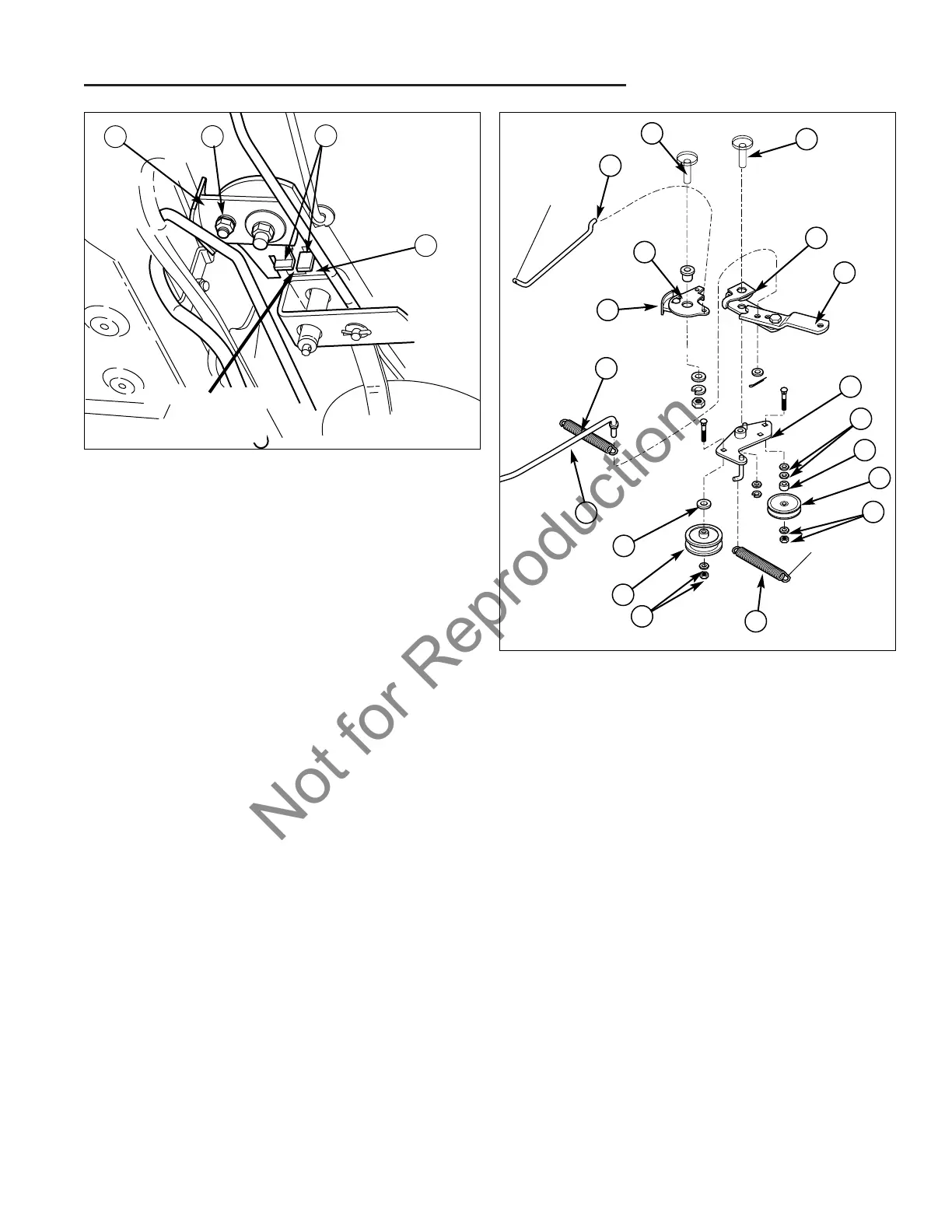
Figure 10. Idler Assembly Detail
A. Cruise Pivot (Frame) J. Washer & Nut
B. Lock Plate Bracket K. V-Idler Pulley
C. Cruise Rod L. Spacer
D. Brake Pedal Spring M. Washer, 3/8
E. Clutch Rod N. Idler Plate
F. Washer, 3/8 Plain O. Pivot Plate
G. Backside Idler Pulley P. Brake Lever
H. Washer & Nut Q. Plate & Pad Assy.
I. Idler Assembly Spring R. Idler Pivot (Frame)
Figure 9. Cruise Control Release Tabs
A. Cruise Release Tabs C. Cruise Lock Cam
B. Brake Cam D. Cam Adj. Bolt
A
B
C
D
NOTE: Idler
Assembly
Removed for
Illustration
Purposes.
1/8” to 3/16”
Gap
5. Remove the locknut and washers securing the cruise
assembly (B, Q, Figure 10) to the cruise pivot (A).
6. Inspect and replace parts as needed. Install in
reverse order of installation. If the lock plate bracket
(B) and plate and pad assembly (Q) are separated,
perform the cruise control adjustment in Section 4
ADJUSTMENTS.
Lock Plate Replacement
1. Block the wheels and disengage the parking brake.
2. Remove the lock plate retainer (P, Figure 8).
3. Loosen the hardware securing the ground speed
pedal assembly (D, Figure 8). Remove and replace
the lock plate (O). Install in reverse order of removal.