12 - 7
12 Hand Controls Service
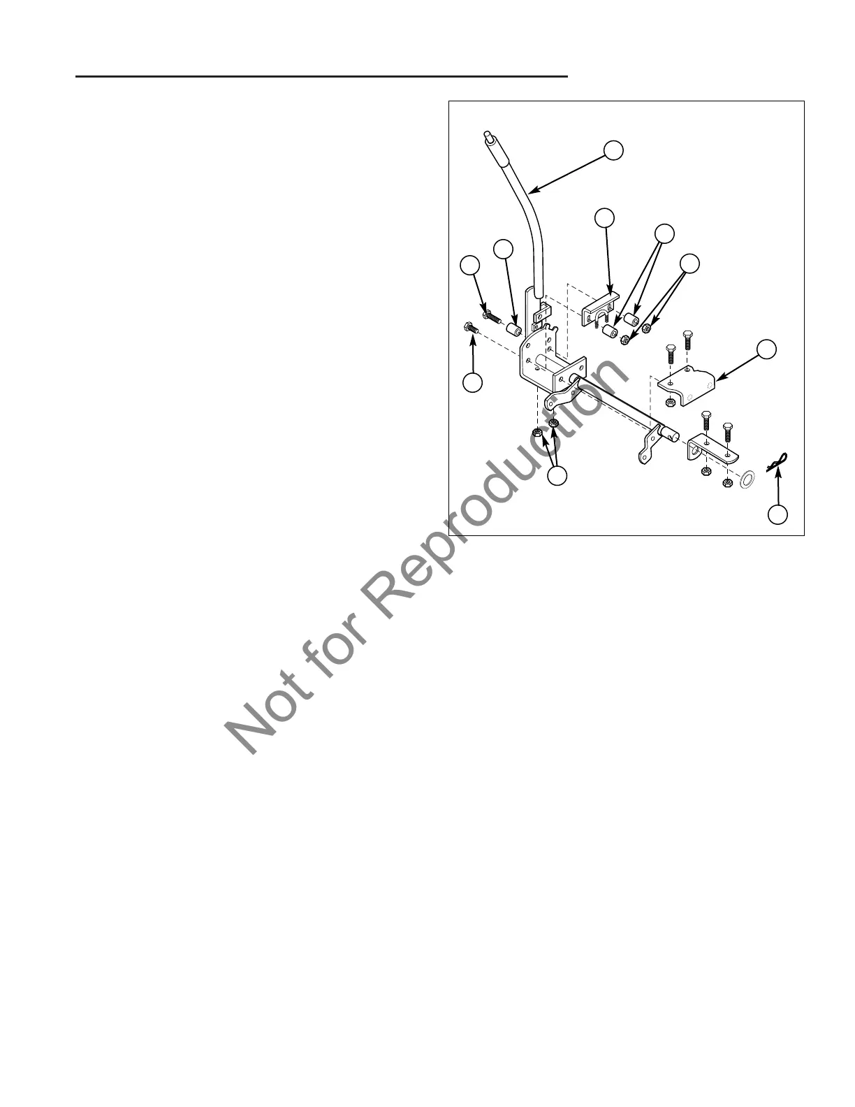
Manual Lift Lever Service
Lift Lever Removal - All Manual Lift Models
The entire lift lever assembly may be easily removed
from the unit for bench inspection and repair:
1. If desired, remove the mower deck from the unit (see
Mower Deck repair section for specific instructions
regarding mower deck removal if necessary), or:
2. Remove the locknuts (D, Figure 2) and spacers (C)
securing the side and bottom of the U-bracket (B).
3. Remove the hair pin clip (F) and washer from the left
side of lift rod.
4. Slide the lift lever assembly straight off the bracket
and pin assembly (E).
5. The lift lever assembly may now be moved to a work-
bench for additional inspection and any required ser-
vicing.
A
H
C
G
B
C
D
E
F
D
Figure 2. Lift Lever Assembly - 44” Models
A. Lift Lever Assy.
B. U-Bracket Assy.
C. Spacers
D. 5/16-18 Locknuts
E. Bracket & Pin Assy.
F. Hair Pin Clip
G. 5/16-18 x 1-1/4 Capscrew
H. 5/16-18 x 1-3/4 Capscrew