8 Steering & Front Wheel Repair
Lower Steering Group
8 - 6
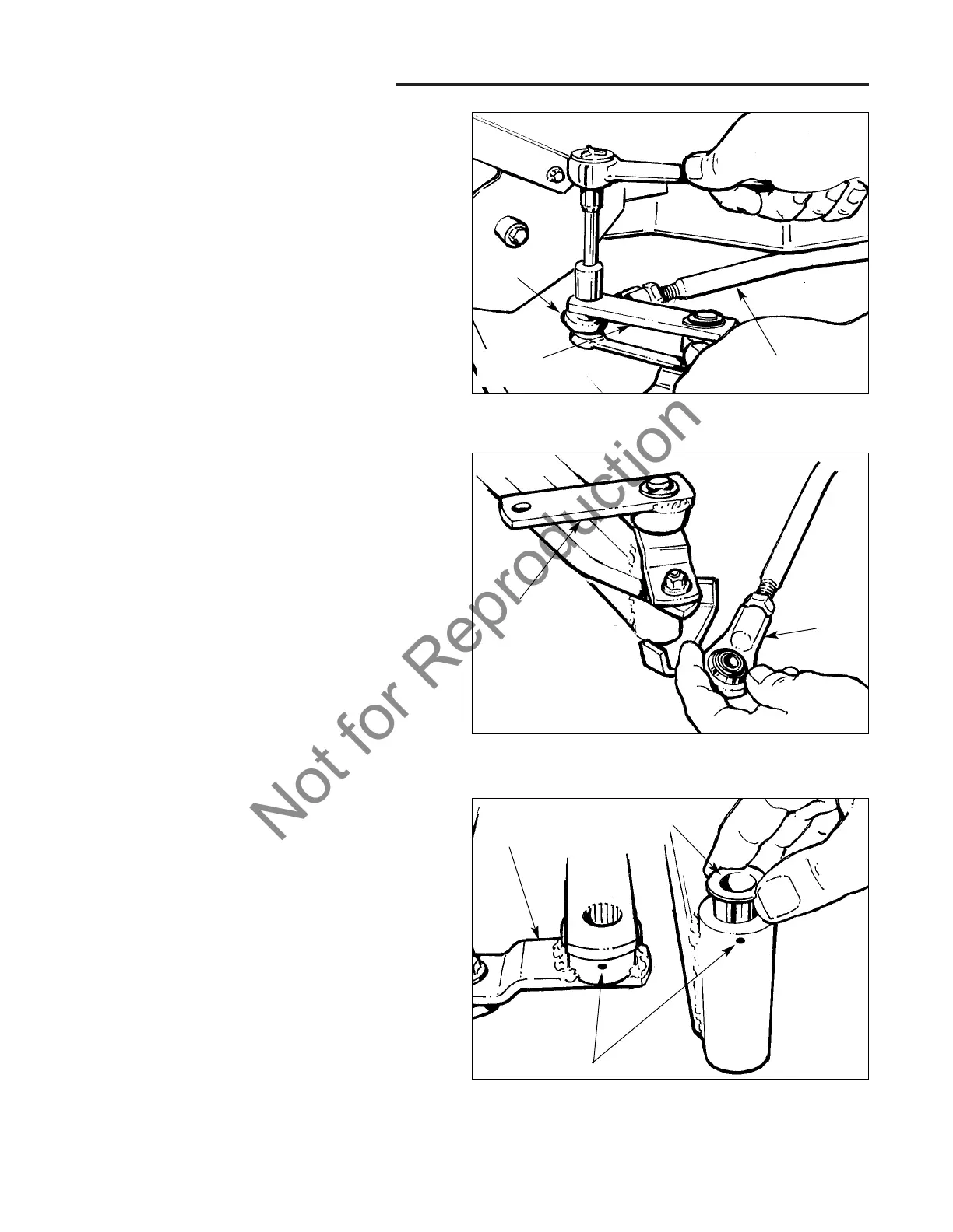
Figure 10. Remove Spindle Shaft Bushings
Punch marks
Figure 8. Remove Rod End
Figure 9. Inspect Rod End
4. Using a 9/16" socket and 9/16" open end or box
wrench, remove the capscrew/washer and flanged
hex nut that secure the steering arm assembly to the
rod end (Figure 8).
NOTE: A spacer is located over the capscrew threads in
the rod opening to permit rotation of the steering arm.
Damage to the spacer or washer caused by excessive
tightening or wear may adversely affect steering, so be
sure to inspect these parts and replace them if neces-
sary before reassembly.
5. The rod end is screwed onto the drag link arm and is
secured in place with a 1/2-20 jam nut.
Rod
End
Drag Link
Steering
Arm
Steering
Arm
Rod
End
Steering
Arm
Bushing
6. Inspect the rod end for free movement/rotation of the
rod end bearing, and replace the rod end if necessary
(Figure 9).
7. To remove the rod end, loosen the jam nut by turning
it clockwise (looking at the end of the drag link shaft)
one or two turns with a 3/4" open-end wrench, and
then unscrew the rod end by turning it counter-clock-
wise.
NOTE: When reinstalling the rod end, be sure to adjust
the length of the drag link arm so that the left and right
spindle stops stop against the axle assembly with full left
and right turns respectively. See the adjustment proce-
dures section for complete details.
8. Tap the left hand steering arm assembly up off the
spindle shaft with a hammer to remove it from the
axle/spindle shaft assembly.
NOTE: It will be helpful to mark the relative positions of
the steering arm, splined spindle shaft, and shaft housing
with punch marks to simplify realignment later (See
Figure 10).
9. Tap the top of the splined spindle shaft down with a
few light hammer blows, and remove the spindle
shaft from the bottom of the axle assembly housing,
noting alignment.
10. With the spindle shaft removed, the bushings can be
removed and inspected for signs of wear (Figure 10).
Use a brass drift or punch to tap out the bushings
from opposite ends of the housing. Replace the
bushings if worn, scored, or cracked.