EasyManuals Logo

Simrad CX34-DE NavStation User Manual

Simrad CX34-DE NavStation
62 pages
To Next Page IconTo Next Page
To Previous Page IconTo Previous Page
Page #51 background imageLoading...
Page #51 background image
Pull cord
White (coax)
Green (shield)
Yellow
Blue
Green
Brown
NC
White
Red
Pull cord
Blue
Green
Yellow
Violet
Pull cord 1
Orange
Red
Pull cord 1
1
2
3
45
6
7891011
12
13
14
15
16
17
18
CX34/44/54-series Installation 1-45
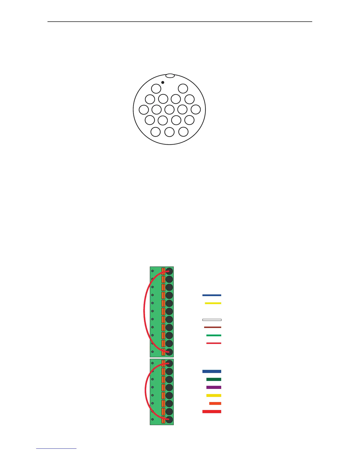
1.13.4 Connector’s pin numbers and wire colors
The connecting cable is supplied with the radar scanner. The 18-pin round
connector is connected to the main unit’s receptacle marked RADAR:
(seen from solder side)
– refer to section 1.8 for details on pin numbers.
The connector at the other end of the connecting cable is for the radar scanner,
and consist of the following pin numbers and wire colors:
Wire colors and pin numbers for the DX45 and DX60 Radar scanner

Questions and Answers:

Question and Answer IconNeed help?

Do you have a question about the Simrad CX34-DE NavStation and is the answer not in the manual?

Simrad CX34-DE NavStation Specifications

General IconGeneral
BrandSimrad
ModelCX34-DE NavStation
CategoryMarine GPS System
LanguageEnglish

Related product manuals