LONGITUDINAL
FEED
LINKAGE (Continued)
SETTING
1:
(To
obtain
equal
distance)
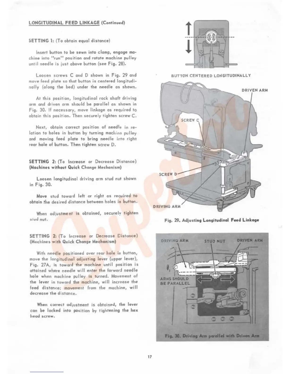
Insert button to be sewn into clomp, engage
maa
chine
into
urun
11
position
and
rotate
machine
pulley
until
needle
is
just
above
button
(see
Fig.
28).
Loosen
screws
C and D shown
in
Fi
g.
29
and
move feed plate
so
that button
is
centered
longitvdi~
nally (along tho bod) under tho noodle
as
shown.
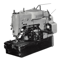
At
this
position,
longitu
dinal
rock
shaft
driving
arm
and
driven
arm
shou
ld be paral l
el
as shown in
Fig. 30. If
necessary,
move linkage
as
required to
obtain
this
posit1on. Then
securely
tighten
screw
C.
Next, obtain correct position
of
needle in ,
...
lotion to
holes
in button by turning
moch
i
n~
pulley
and moving feed
plate
to
bring
needle
irto
right
roar
halo
of burton.
Then
tighten
screw
D.
SETTING 2: (To Increase or
Decrease
Distance)
(Machines without Quick Change Mechanism)
Loosen longi
tu
dinal driving arm
stud
nut shown
in
Fig.
30.
Move stud toward
left
or right as recuired to
obt
ain
the
desired
distance
between
holes
in
button.
When
adjustment is obtained, securely ti9hten
~•uJ
nut.
SETTING 2:
(To
Increase
or
Decr,.os"
CIStanco)
(Machines with Quiok Change Mechanism)
With
needle positioned over rear hole
in
button,
move the longitudinal ad j
usti
ng lover (upper
lever),
Fig.
27A,
In
toward
the
machine until position
Is
attain
ed
where
need
le will
enter
the
forward
need
le
hole
wh
on
machine pulley
is
turned. Movement
of
the lever in toward the mochin&,
will
increase the
feed
distance;
movement
from
the
machine,
wil
l
decrease
the
diston~e.
When
correct ad,u5hnent
is
obtoinPd, the lever
can
be
locked into
position
by
tightening
tho
hex
head
screw.
t7
BUTTON CENTERED LONGITUDII'IALL Y
r
DRIVEN ARM
Fig. 29. Adju>ti
ng
Longitudinal F
..
d
Linkage
DRIVING ARM
STUD
HUT
DRIWII
Alllf
Fig.
30.
o.lvi
..
Ani