Page 112
EN
BN
WH
BU
BK
BU
CS/PS
BN
X3
1
X2
2
3
4
+
SL2
1
2
3
4
1
2
3
4
X4
BU
BK
SL2
2,4W
179-990-700
1
2
3
CS/PS
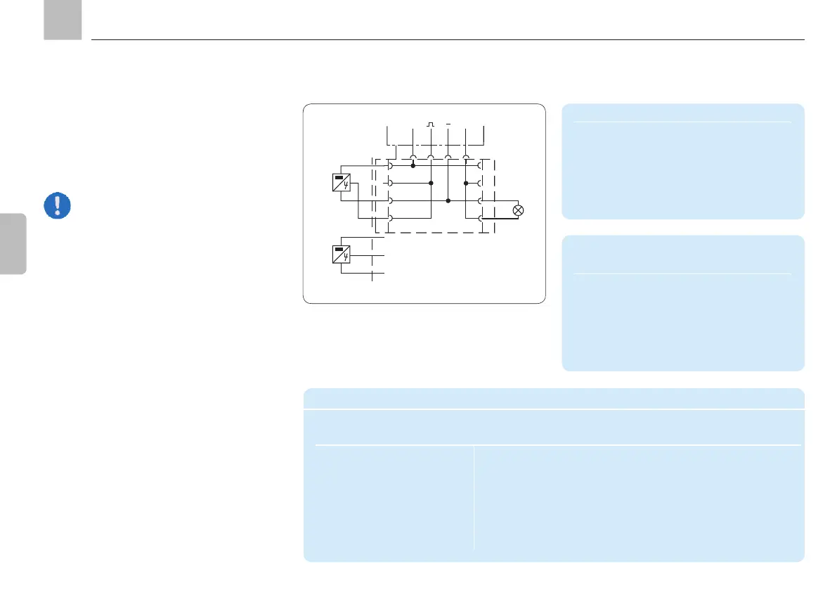
17.1 Connectivity for timer operation
control, piston detector and indicator
light
Connection for piston detector/pressure
switch CS
PIN Code Assignment
1 Voltage ( + )
2 CS/PS Pressure/piston detector (signal)
3 ( - )
4 CS/PS Pressure/piston detector (signal)
A double-pin plug with a special cable
adapter is required for this application.
Accessories
Description Data Order No.
M12x1 circular connector
with cable for connecting
to piston detector and an
external fault indicator
Cable set
Two-way distributor
(for connecting to the M12x1 plug on the
pump with 2x M12x1 outputs for piston
detector and separate indicator lamp)
179-990-719
179-990-700
Connection for fault notification SL2
PIN Code Assignment
1
2
3 SL2 “Fault” indicator light ( - )
4 SL2 "Fault" indicator light ( + )
17. Accessories
KFGS
AB