April 2006
SKYJACK, Page 16
Section 2 - Operation Component Identification
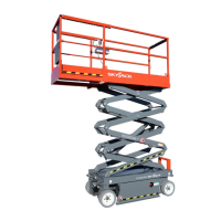
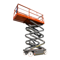
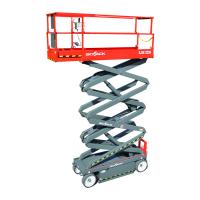
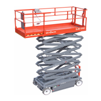
SJ800 - E Series
Battery Powered
2.2 Component Identification
The following descriptions are for identification,
explanation and locating purposes only.
2.2-1 Battery Connectors
This connector is located at the front of the pull-out
battery tray.
Figure 2-1. Battery Connectors
1. Battery Connectors - These connectors, when
separated, disconnect the batteries and all power
to the platform and base controls. In the event of
an emergency or when performing maintenance,
grasp the handle and pull the connectors apart.
2. Battery Lockout - This lockout is provided to
prevent unauthorized use and for maintenance
purposes.
1
2
2.2-2 Electrical Panel
This panel is located in the hydraulic/electric cabinet. It
contains the following controls:
Figure 2-2. Electrical Panel
1. Hourmeter - This gauge activates when a function
is selected. It records the accumulated time of
operation of the aerial platform.
2. Circuit Breaker Resets - In the event of a power
overload or positive circuit grounding, the circuit
breaker will pop out. Make the necessary
corrections, then depress the push-button to reset.
2.2-3 Base Controls
These controls are located outside of the rear of the
hydraulic/electric cabinet. It contains the following
controls:
Figure 2-3. 1500W AC Inverter
1. Platform UP/DOWN Toggle Switch - This toggle
type switch raises or lowers the platform to a
desired height.
2. Emergency Stop Button - This red “mushroom-
head” shaped button switch is designed to
disengage power to both the platform and base
controls.
1
2
1
2