Page 10
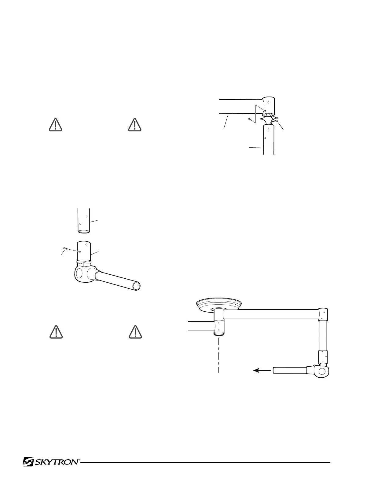
Figure 5. VST to RAA Installation
Figure 6.
Figure 4. Balance Mechanism
CAUTION
The 6mm mounting screws for attaching
the VST to the radial arm may be dif-
ferent lengths. Observe any color code
markings and make sure the proper
screws are installed in the proper holes
to avoid any damage to the electrical
components.
b. Observe the wire colors and connect the wires
from the radial arm to the corresponding BOM/VST
wires using crimp connectors. See figure 5.
4. Lightheads
Model LED7 Lighthead
Refer to Model Identification for correct lighthead
placement.
a. To make it easier to install the lighthead,
locate the support arm of the balance mechanism
so that it points inward toward the ceiling cover.
This will prevent the radial arm from moving when
installing the lighthead. See figure 6.
b. Remove the four (4) screws from the lighthead
support arm.
c. Install the lighthead mounting collar onto the
support arm and secure with the screws previously
removed. See figure 7.
POINT SUPPORT ARM
TOWARD CENTER LINE
c. Insert the vertical support tube into the radial
arm receptacle. Observe any screw color codes,
apply Loc-Tite to screw threads, and secure the
BOM/VST assembly with the 6mm mounting screws.
Repeat procedure for any remaining BOM/VST
assemblies.
3. Vertical Support Tubes/Balance Mecha-
nism
NOTE
Determine correct placement for each
Balance Mechanism(BOM)/Vertical
Support Tube(VST) on the radial arm
assembly. The longest VST goes into
the top radial arm.
WARNING
Apply Blue Loc-Tite to all of the 6mm
mounting screws and use a 4mm allen
wrench to tighten the screws.
a. Install the VST on the BOM, apply Blue Loc-
Tite to screw threads and secure VST with the allen
screws provided. See figure 4.

 Loading...


