8. Serial Interface
Configuration and operation of the Si5341/40 is controlled by reading and writing registers using the I
2
C or SPI interface. Both of these
serial interfaces are based upon 8-bit addressing, which means that the page byte must be written every time you need to access a
different page in the register map. See the PGE byte at register 0x0001 for more information. The I2C_SEL pin selects I
2
C or SPI
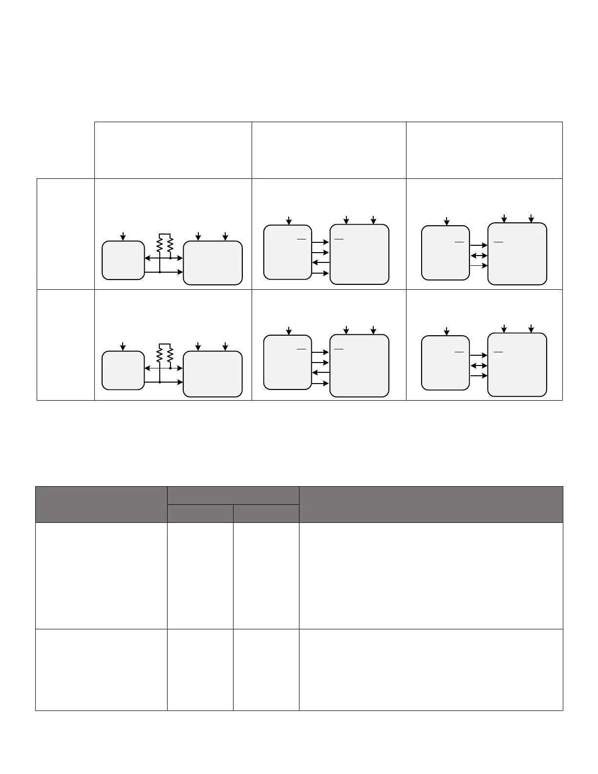
operation. The Si5341/40 supports communication with a 3.3 V or 1.8 V host by setting the IO_VDD_SEL (0x0943[0]) configuration bit.
The SPI mode supports 4-wire or 3-wire by setting the SPI_3WIRE configuration bit.
VDDA
VDD
1.8V3.3V
Host = 3.3V
Host = 1.8V
I
2
C
I2C_SEL pin = High
IO_VDD_SEL = VDD
IO_VDD_SEL = VDD
I2C_SEL pin = Low
SPI
HOST
1.8V
SDI
SDO
CS
CS
SDO
SDI
SCLK
SCLK
Si5341/40
I
2
C
HOST
1.8V
VDDA
SCLK
SDA
1.8V
VDD
1.8V3.3V
SPI
HOST
1.8V
SDIO
SDIO
CS
CS
SCLK
SCLK
SPI_3WIRE = 0
SPI 4-Wire SPI 3-Wire
I2C_SEL pin = Low
SPI_3WIRE = 1
IO_VDD_SEL = VDD
IO_VDD_SEL = VDDA
IO_VDD_SEL = VDDA IO_VDD_SEL = VDDA
SCLK
SDA
(Default) (Default)
VDDA
VDD
1.8V3.3V
(Default)
VDDA
VDD
1.8V3.3V
SPI
HOST
3.3V
SDI
SDO
CS
CS
SDO
SDI
SCLK
SCLK
I
2
C
HOST
3.3V
VDDA
SCLK
SDA
3.3V
VDD
1.8V3.3V
SPI
HOST
3.3V
SDIO
SDIO
CS
CS
SCLK
SCLK
SCLK
SDA
VDDA
VDD
1.8V3.3V
Si5341/40 Si5341/40
Si5341/40
Si5341/40
Si5341/40
Figure 8.1. I
2
C/SPI Device Connectivity Configurations
The following table lists register settings of interest for the I
2
C/SPI.
Table 8.1. I
2
C/SPI Register Settings
Register Name
Hex Address [Bit Field]
Function
Si5341 Si5340
IO_VDD_SEL 0x0943[0] 0x0943[0]
The IO_VDD_SEL configuration bit optimizes the V
IL
, V
IH
, V
OL
,
and V
OH
thresholds to match the VDDS voltage. By default the
IO_VDD_SEL bit is set to the VDD option. The serial interface
pins are always 3.3 V tolerant even when the device's VDD pin
is supplied from a 1.8 V source. When the I
2
C or SPI host is
operating at 3.3 V and the Si5340/41 at VDD = 1.8 V, the host
must write the IO_VDD_SEL configuration bit to the VDDA option.
This will ensure that both the host and the serial interface are
operating at the optimum voltage thresholds.
SPI_3WIRE 0x002B[3] 0x002B[3]
The SPI_3WIRE configuration bit selects the option of 4-wire or
3-wire SPI communication. By default the SPI_3WIRE configura-
tion bit is set to the 4-wire option. In this mode the Si5341/40 will
accept write commands from a 4-wire or 3- wire SPI host allowing
configuration of device registers. For full bidirectional communica-
tion in 3-wire mode, the host must write the SPI_3WIRE configu-
ration bit to “1”.
If neither serial interface is used, leave pins I2C_SEL, A1/SDO and A0/CS disconnected and tie SDA/SDIO and SCLK low.
Si5341, Si5340 Rev D Family Reference Manual • Serial Interface
Skyworks Solutions, Inc. • Phone [781] 376-3000 • Fax [781] 376-3100 • sales@skyworksinc.com • www.skyworksinc.com
37 Rev. 1.3 • Skyworks Proprietary Information • Products and Product Information are Subject to Change Without Notice • July 26, 2021 37