Page 34 of 42
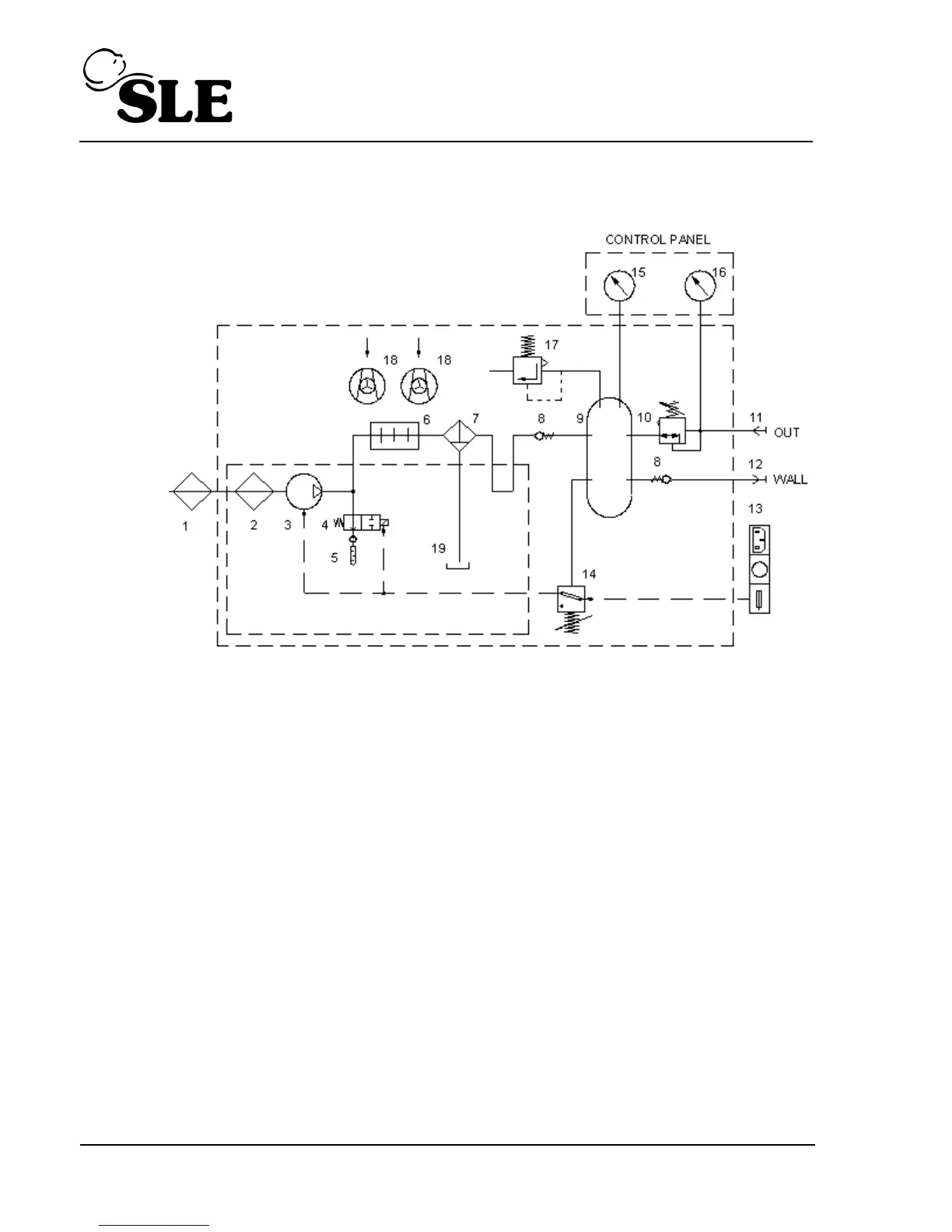
14. Pneumatic Diagram
1. Intake filter 14. Pressure switch
2. Filter inserts 15. Index of air humidity
3. Compressor 16. Performance gauge
4. Solenoid valve 17. Pressure relief valve
5. Sound absorber 18. Fan
6. Cooler 19. Water tray
7. Micro filter with water trap
8. Check valve
9. Air tank
10. Pressure regulator
11. Air outlet
12. Air inlet
13. Mains input, power switch, primary fuses