22
Installation Manual
SMA Solar Technology AG
DC-CMB-IA-U15-xx-en
6 Electrical Connection
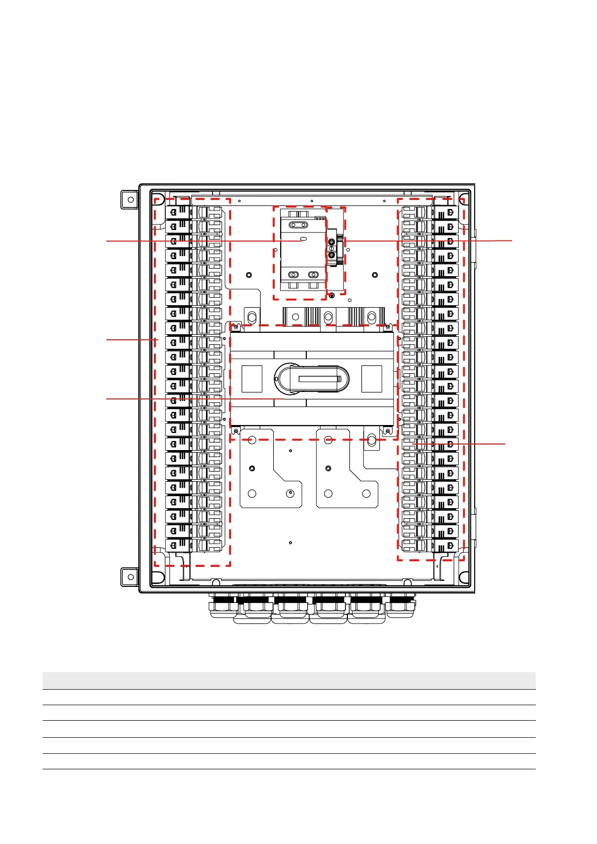
6.3.4 Overview of the Connection Area DC-CMB-U15-24
The features of the Combiner Box are dependent on the order option. The maximum configuration of the Combiner Box is
shown in the overview diagrams.
Combiner Box with cable glands for the string cables:
Figure 11: Connections (as exemplified in the DC-CMB-U15-24)
Position Designation
A Positive input string fuse holder
B Negative input string fuse holder
C
Surge protection device
D Switch
E Grounding terminal
A
D
C
E
B