10
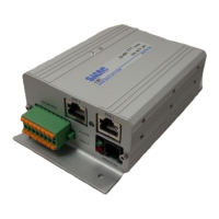
Figure 6. Analog input electrical schematic.
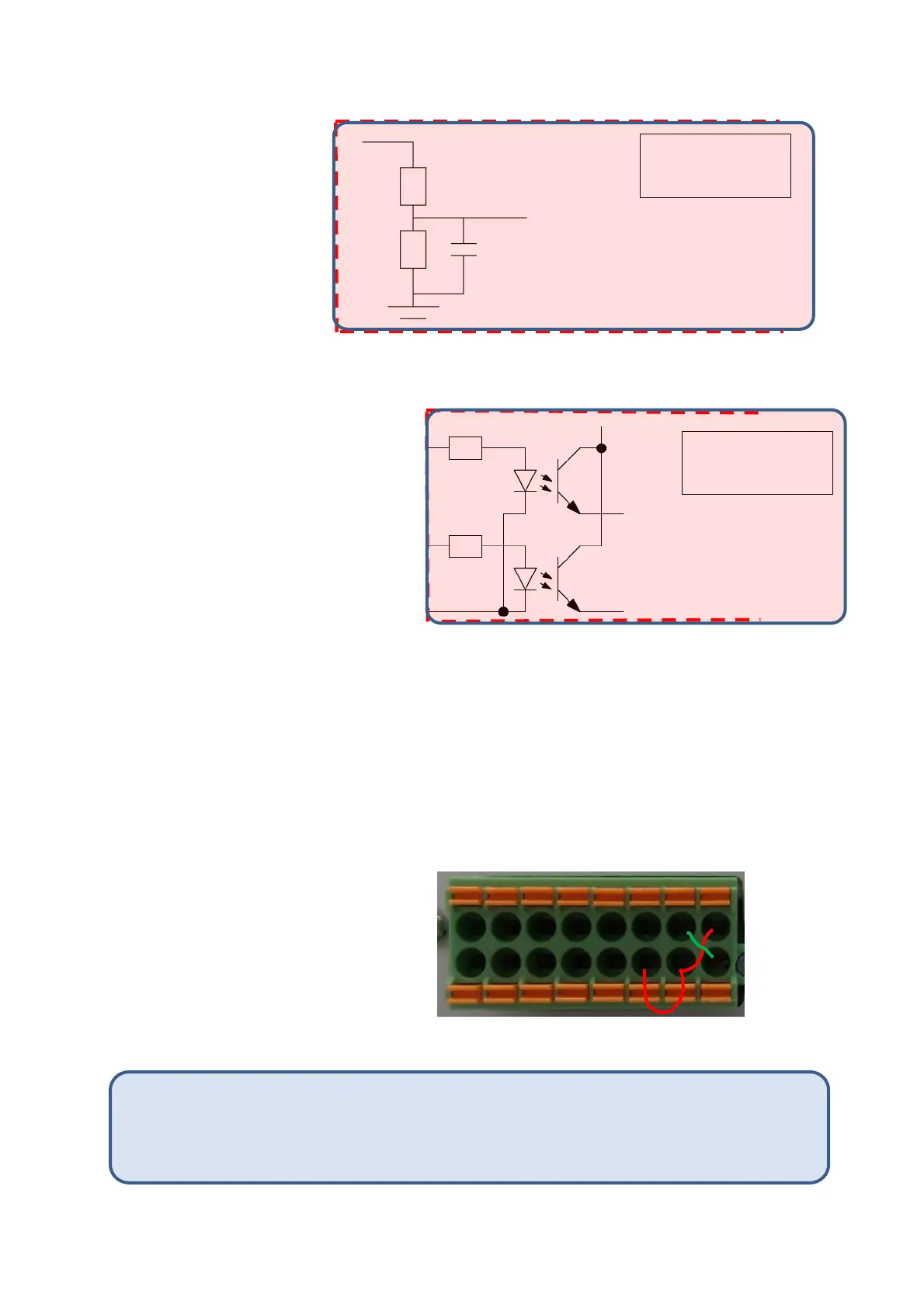
Figure 7. STO electrical schematic.
2.1.3 Disabling the STO (OPTIONAL)
The CBC drive cannot be operated unless voltages are applied at both STO 1 and STO 2 as in
Figure 7. In case the STO functionality is not required, the on-board +5VDC can be applied to
the STO inputs conveniently without needing an external voltage source. This can be done by
applying jumper connection on the I/O and STO connector as shown in Figure 8.
Figure 8. Disabling the STO on the I/O and STO connector.
The CBC-EIP includes a Safe Torque Off (STO) circuit. The STO is a safety system that prevents motor
torque in an emergency event while CBC-EIP remains connected to the power supply. When STO is
➢ Connect pins 8, 14, 15 together
➢ Connect pins 7, 16 together
Note: The Inputs/Outputs to the controller should be supplied with separate power supply
from the field (24V). STO connection should have separate power supply or with 5V onboard
supply. The ground pin 7 should be daisy chained to all the controllers in the network to
facilitate common ground path. (Failure to do this will affect ethernet connection)