8
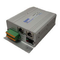
Table 2. Details on connectors in Figure 3
POWER (Terminal block header, 5 mm pitch)
1: Ground (DC power Return)
2: +24VDC/+48VDC supply
3: Actuator winding phase U
4: Actuator winding phase V
5: Actuator winding phase W
6: Ground
ENCODER (Standard D-SUB 15 pin, female)
1: A+
2: I+
3: B+
4: +5V
5: +5V
6: +5V
9: A-
10: I-
11: B-
12: Ground
13: Ground
I/O AND STO
(Manufacturer: Phoenix Contact, P/N:
1790357)
1: Digital input 1
2: Digital input 2
3: Digital input 3
4: Digital input 4
5: Digital input common
6: Analog input 1
7: Ground
8: +5VDC supply
9: Digital output 1
10: Digital output 2
11: Digital output 3
12: Digital output 4/STO Feedback (only
available upon request)
13: Digital output common
14: STO 1
15: STO 2
16: STO common
1: CAN high
2: CAN low
3: RS232 RX
4: RS232 TX
5: Ground
6: NC
ETH 1 & ETH 2 (Standard RJ-45 Ethernet
jacks)
2.1.2 I/O and STO electrical schematics
Note: The Inputs/Outputs to the controller should be supplied with separate power supply
from the field (24V). STO connection should have separate power supply or with 5V onboard
supply. The ground pin 7 should be daisy chained to all the controllers in the network to
facilitate common ground path. (Failure to do this will affect ethernet connection)