6| INSTALLING YOUR SMART BOARD 685IX PREMIUM INTERACTIVE
WHITEBOARD SYSTEM
Installing the ECP on the interactive whiteboard’s frame
Before you install the interactive whiteboard, temporarily attach the ECP to the
lower-right of the frame using self-tapping screws. Later in the installation, you’ll
permanently attach the ECP after connecting all of its cables.
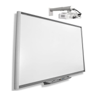
To install the ECP 1. Lay the interactive whiteboard on its back on a
flat surface.
2. Position the ECP module on the bottom frame
4 1/2" (11.4 cm) from the inside edge of the right
frame.
3. Using the ECP as a template, drill two 1/8" holes
in the bottom frame.
4. Using a Phillips No. 2 screwdriver, attach the
ECP to the frame with two included self-tapping
screws.
5. Remove those two screws and the ECP. Put the
screws in a safe location and keep the ECP
nearby to use in a later procedure.
IMPORTANT
You must remove the ECP so you can connect cables to it before you
permanently attach it to the interactive whiteboard’s frame.
6. Place the interactive whiteboard in a safe location until later in the installation.
Installing the ECP and projector cables and the guest
computer harness
Because the ECP cables, projector cables and guest computer harness are installed
inside the wall mount frame, behind the interactive whiteboard, you must install them
now.
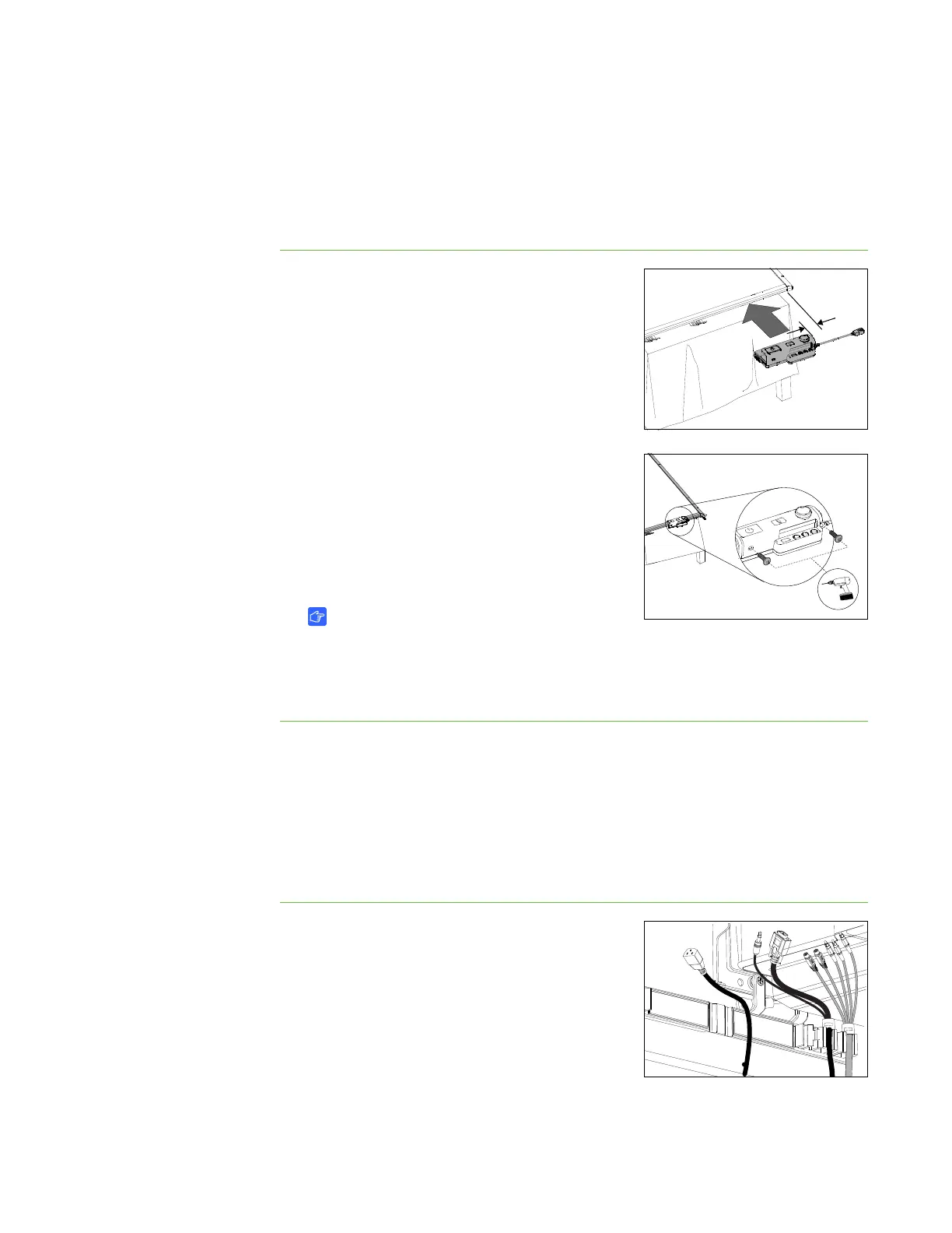
To install the cables to the
projector cable support
1. Position the five-connector end of the ECP
cable and the two-connector end of the guest
computer harness on the right end of the wire
management clip, and then push them into their
slots in clip.
2. Place the female end of the power cable to the
left of the cable clips leaving enough length to
connect to the projector’s power connector.
 Loading...