HGM1790N Genset Controller User Manual Page 14 of 31
6. WIRING CONNECTION
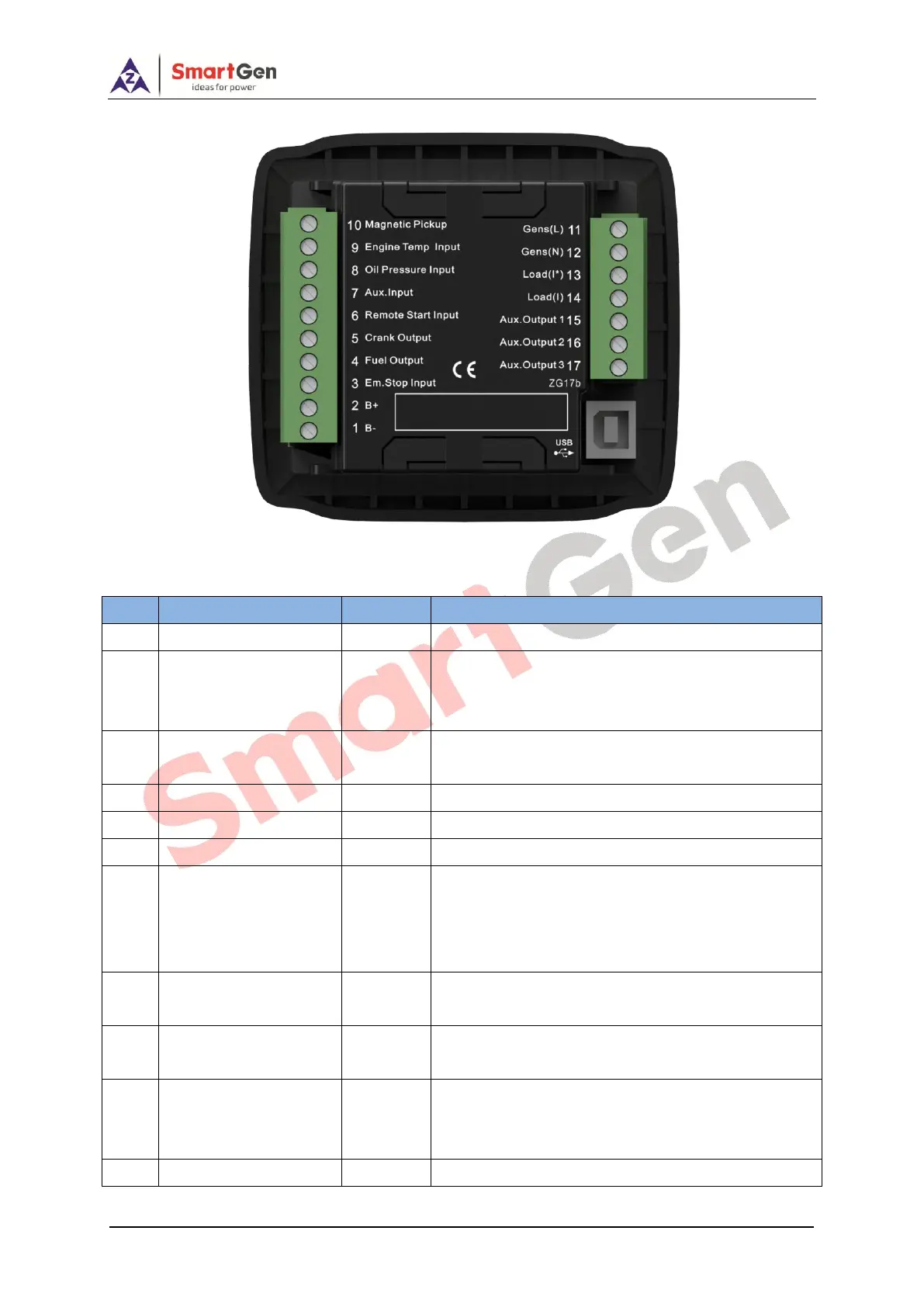
Fig.2 Controller Back Panel
Table 6 Terminals Description
Connect to negative of starting battery
Connected to positive of starting battery. If wire
length is over 30m, better to double wires in parallel.
Max. 20A fuse is recommended.
B+ voltage input is active, and connected to
emergency stop normal closed button.
B+ is supplied by No.3 point, rated 1A.
B+ is supplied by No.3 point, rated 1A.
Ground connected is active (B-)
Ground connected is active (B-) if it is configured as
digital input.
Connect to low fuel level coil or fuel level resistor
type sensor if it is configured as level sensor.
Connect to low oil pressure coil or resistor type
sensor.
Connect to high water/cylinder temp. coil or
temperature resistor type sensor.
Connect to speed sensor, and shielded wire is
recommended.
The other end of speed sensor is connected to B-.
Connect to generator voltage output port. (2A fuse is

 Loading...