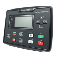
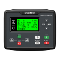
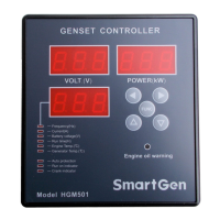
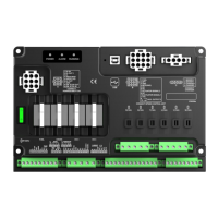
HGM7220N/HGM7220S GENSET CONTROLLER USER MANUAL
HGM7220N/HGM7220S Genset Controller 2019-02-28 Version 1.0 Page 22 of 60
Table 9 - Terminal Wiring Connection
Connected with negative of starter battery.
Connected with positive of starter battery. If wire length
is over 30m, it’s better to double wires in parallel. Max.
20A fuse is recommended.
Connect with B+ via emergency stop button.
B+ is supplied by Terminal 3, rated 16A.
B+ is supplied by Terminal 3, rated 16A.
Connect with starting coil of starter.
B+ is supplied by Terminal 2, rated 8A.
For items please see
Table 11.
Aux. Output 3(16A 250VAC)
Relay NO volt free contact,
rated 16A, volt free contact
output.
Aux. Output 4(16A 250VAC)
Connected with charger starter’s D+ (WL) terminal.
Please hang it up if there is not this terminal.
B+ is supplied by Terminal
2, rated 8A
For items please see
Table 11.
Connect with speed sensor, and shielded wire is recommended.
Speed sensor input, battery
negative electrode has been
connected inside controller.
Connect with temperature sensor
For items please see
Table 13.
Connect with pressure sensor
Connect with fuel level sensor
Ground connected is active (B-)
For items please see
Table 12.
Ground connected is active (B-)
Ground connected is active (B-)
Ground connected is active (B-)
Ground connected is active (B-)
Sensor common port, battery negative electrode has been
connected inside controller.
Ground connected is active (B-)
For items please see
Table 12.
Ground connected is active (B-)
 Loading...
