HGM7220N/HGM7220S GENSET CONTROLLER USER MANUAL
HGM7220N/HGM7220S Genset Controller 2019-02-28 Version 1.0 Page 23 of 60
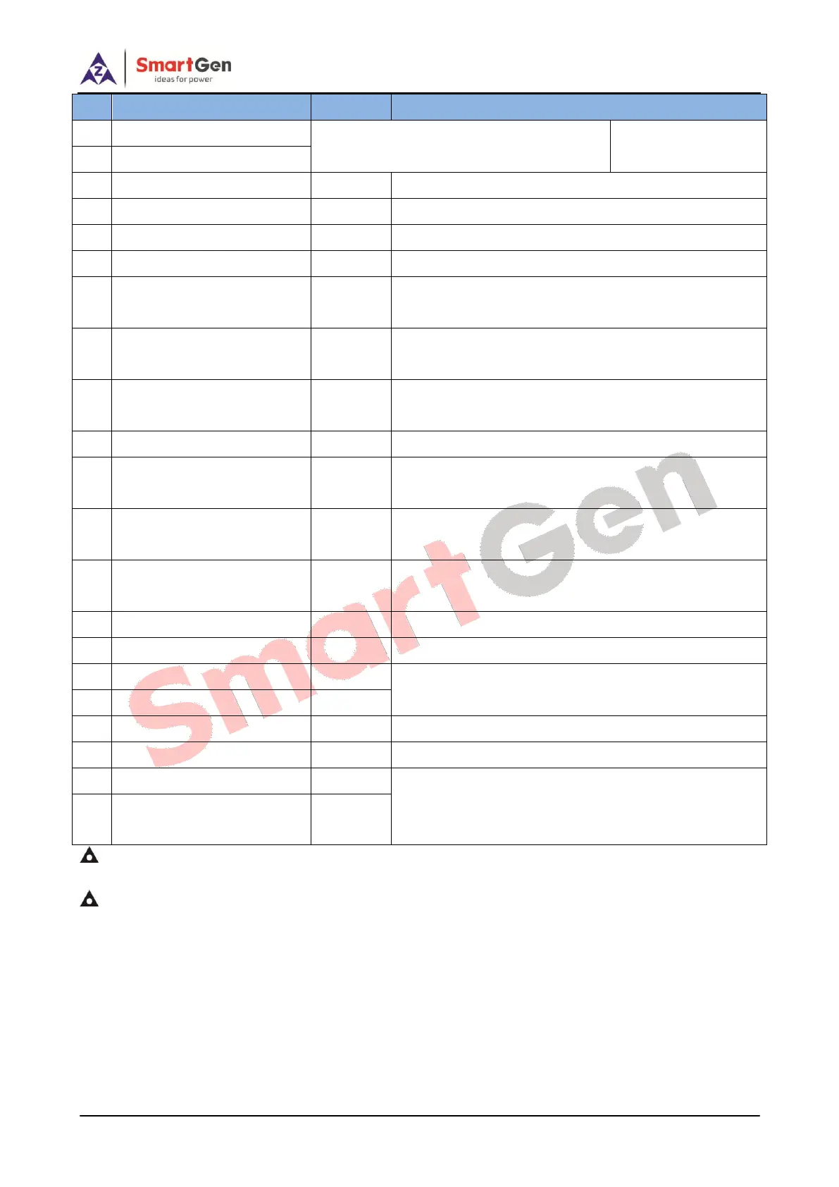
Connected with temp/pressure/fuel level
sensor.
For items please see
Table 13.
CT A-phase Monitoring Input
Outside connected to secondary coil of CT (5A rated).
CT B-phase Monitoring Input
Outside connected to secondary coil of CT (5A rated).
CTC-phase Monitoring Input
Outside connected to secondary coil of CT (5A rated).
Details to see the following installation description.
Gen U-phase Voltage
Monitoring Input
Connected to U-phase output of genset (2A fuse
recommended).
Gen V-phase Voltage
Monitoring Input
Connected to V-phase output of genset (2A fuse
recommended).
Gen W-phase Voltage
Monitoring Input
Connected to W-phase output of genset (2A fuse
recommended).
Connected to N-line output of genset.
Mains R-phase Voltage
Monitoring Input
Connected to R-phase of mains (2A fuse
recommended).
Mains S-phase voltage
monitoring input
Connected to S-phase of mains (2A fuse
recommended).
Mains T-phase voltage
monitoring input
Connected to T-phase of mains (2A fuse recommended).
Connected to N-line of mains.
If 120Ω resistor is needed, short connect 44 and 46.
120Ω shielding wire is recommended with single end
ground connected.
120Ω shielding wire is recommended with single end
ground connected. Between CAN L and CAN H there is
already 120Ω resistor inside the controller.
NOTE: USB ports in controller rear panel are programmable parameter ports, and users can directly configure the
controller on PC.
NOTE: Modem expansion module can be connected from the rear panel.
 Loading...