EasyManua.ls Logo

SMC Networks HRZ001-L - Part 2

SMC Networks HRZ001-L
98 pages
To Next Page IconTo Next Page
To Previous Page IconTo Previous Page
Loading...
HRX-OM-I051
Chapter 8 Appendix
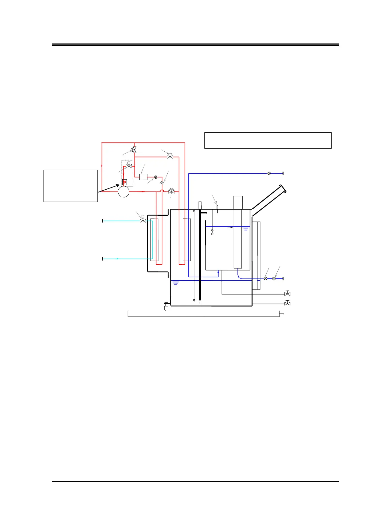
HRZ Series 8.3 Flow Chart
8-17
8.3.2 Part 2
HRZ001-L HRZ002-L HRZ004-L HRZ008-L
HRZ001-L1 HRZ002-L1 HRZ004-L1 HRZ008-L1
HRZ001-L2 HRZ002-L2 HRZ004-L2 HRZ008-L2
Figure 8-5 Flow Chart
Facility water circuit
Circulating fluid circuit
Compressor
Refrigerant pressure
gauge (high)
Filter dryer
Thermal
fuse
Internal
pump
Circulating pump
Temp.
sensor
Press.
sensor
Circulating fluid level gauge
Flow sensor
Circulating fluid return
(Rc3/4
w/ plug
)
Condenser
Evapor
ator
Sub tank drain port
(Rc3/8
w/ plug
)
Level
switch
Level
switch
Refrigerant
pressure
switch
Circulating fluid supply
(Rc3/4
w/ plug
)
Main tank drain port
(Rc3/8
w/ plug
)
Facility water outlet
(Rc1/2
w/ plug
)
Facility water inlet
(Rc1/2
w/ plug
)
leakage
switch
Drain pan port
(Rc3/8
w/ plug
)
Circulating fluid fill port
Refrigerating circuit
Electron
expansion
valve
Electron
expansion
valve
Electron
expansion
valve
Main tank
Sub tank
Refrigerant
solenoid
valve
Water regulating valve
Water
*1
Inside of dashed line,
only HRZ008-L and
HR008-L1 are
applicable.
*1 : For HRZ004-L* and HRZ008-L*, electron
expansion valve is thermo static expansion valve

Table of Contents

Related product manuals