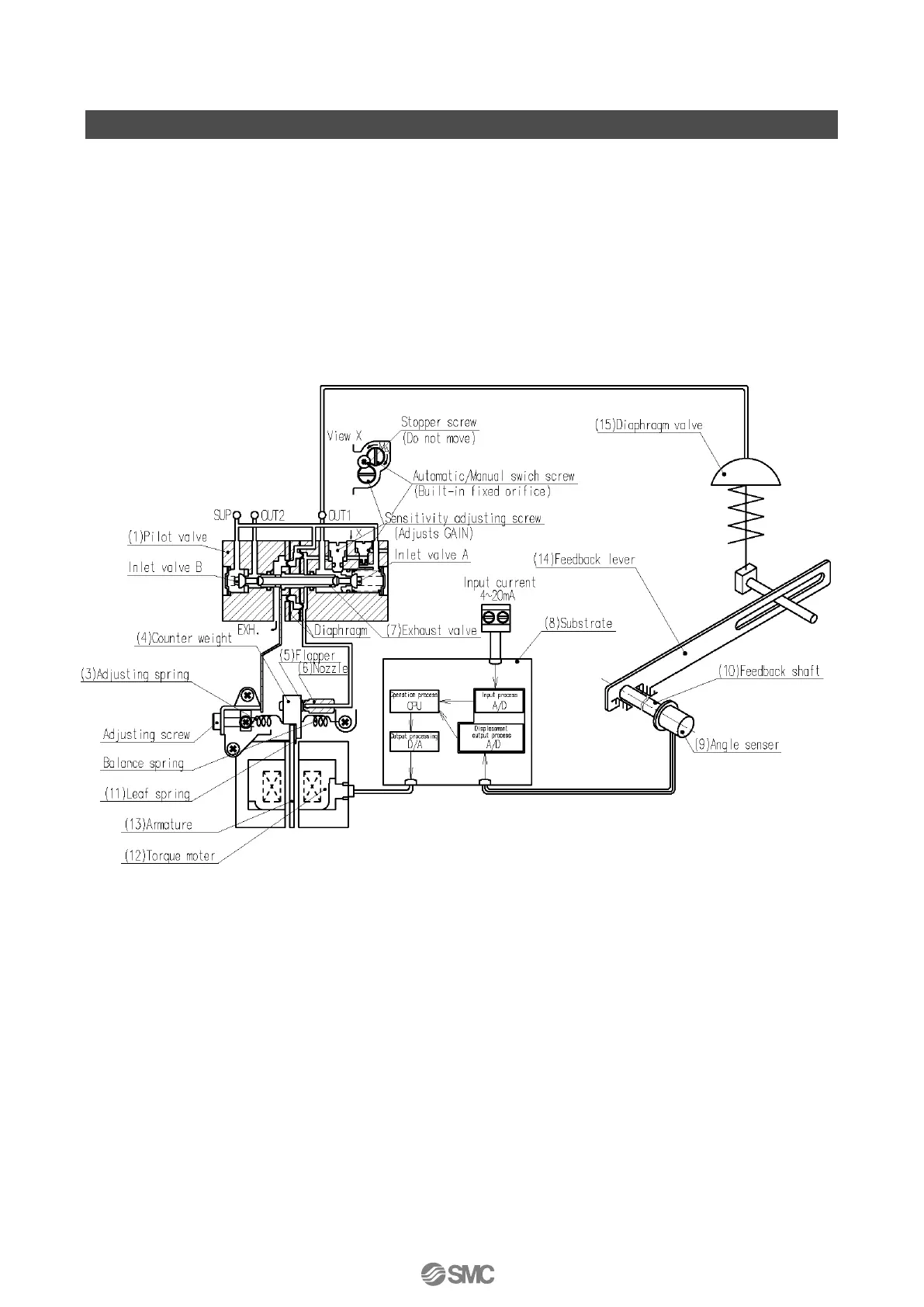
Operating Principle
When the input current (4 to 20mADC) increases, the current which is applied to the coil of the
torque motor (12) through the input, operation and output processing circuits (8) changes, causing
the armature (13) to start rotating with the fulcrum of the leaf spring (11). Along with this, a gap is
created between nozzle (6) and flapper (5), and nozzle back pressure decreases.
As a result, exhaust valve (7) in pilot valve (1) moves to the right, and pressure of OUT1 increases
which makes diaphragm valve (15) move. The movement of diaphragm valve (15) is conveyed to
deflection processor circuit of substrate (8) via feedback lever (14), feedback shaft (10) and angle
sensor (9).
Fig. 3
 Loading...