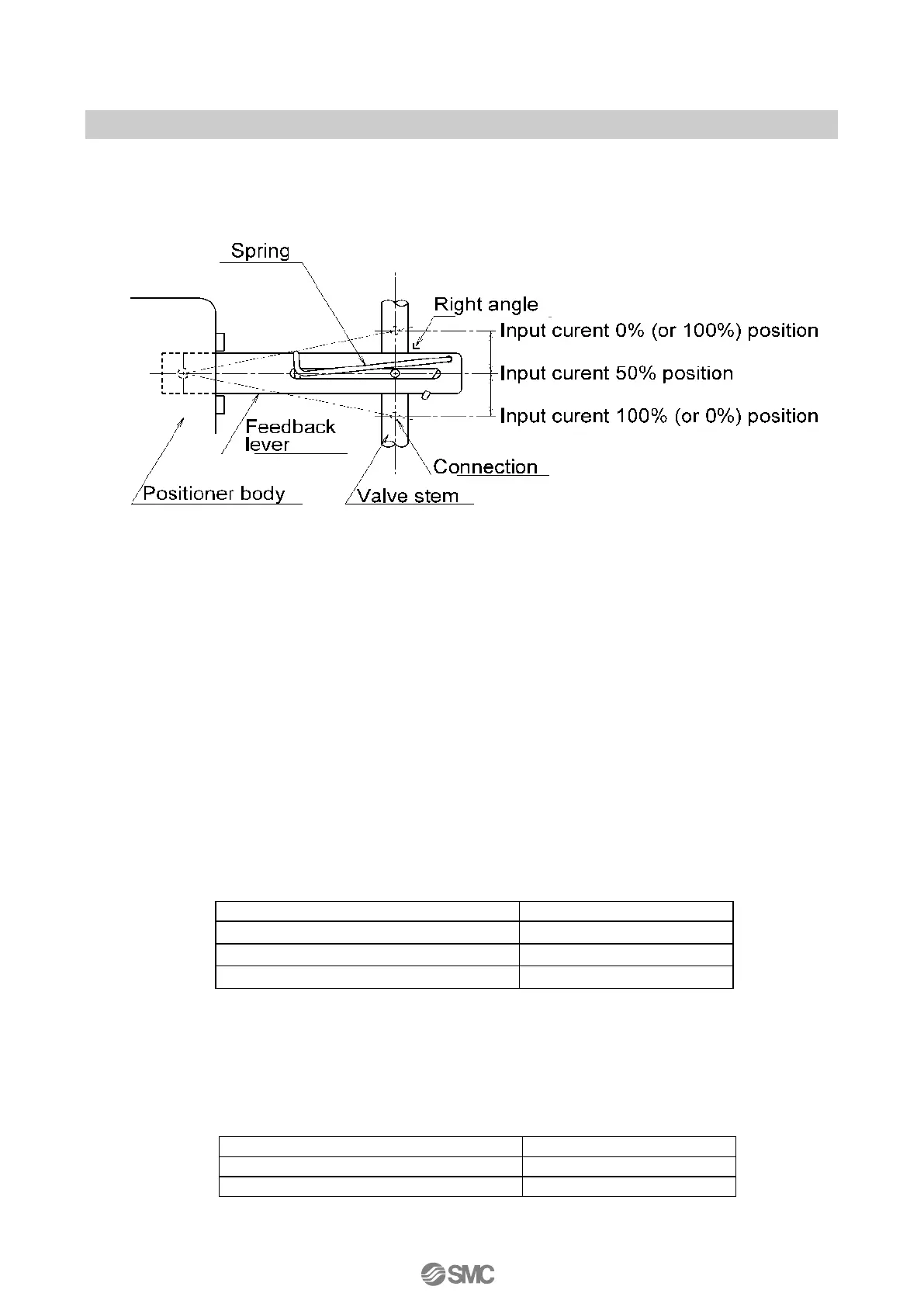
■Connection of Feedback Lever
*2
(1) Attach to the positioner that the valve stem and feedback lever form the right angle when the
input current is 50% (distribute evenly with 50% input current set as the reference).
(2) Attach to the positioner that the operation angle of feedback lever is within the range of 10
o
to
30
o
.
2: Do not impact on the feedback shaft of the positioner when the feedback lever connected with the valve
stem or installed in the positioner.
3: The installation direction of spring need not be changed by the difference of the direction of operation
unlike the IP8000 type.
■Feedback Lever Unit
3 type of feedback lever unit are prepared for actuators with difference stroke.
■Body Cover Unit
2 types of body cover unit can be selected. These can be ordered for replacement. Cover with
window to check LCD is optional.
 Loading...