2. Check angle of
feedback lever
The angle of the feedback lever unit connected to the valve stem
is checked. The calibration explained in section 4 can be
performed if the LCD display is between -30 and 30 in the
operation range of the actuator, but may not satisfy the specified
value of linearity. Therefore, as described in “■Connection of
Feedback Lever”, mount the positioner so that the feedback lever
is symmetrical about the center
*4
.
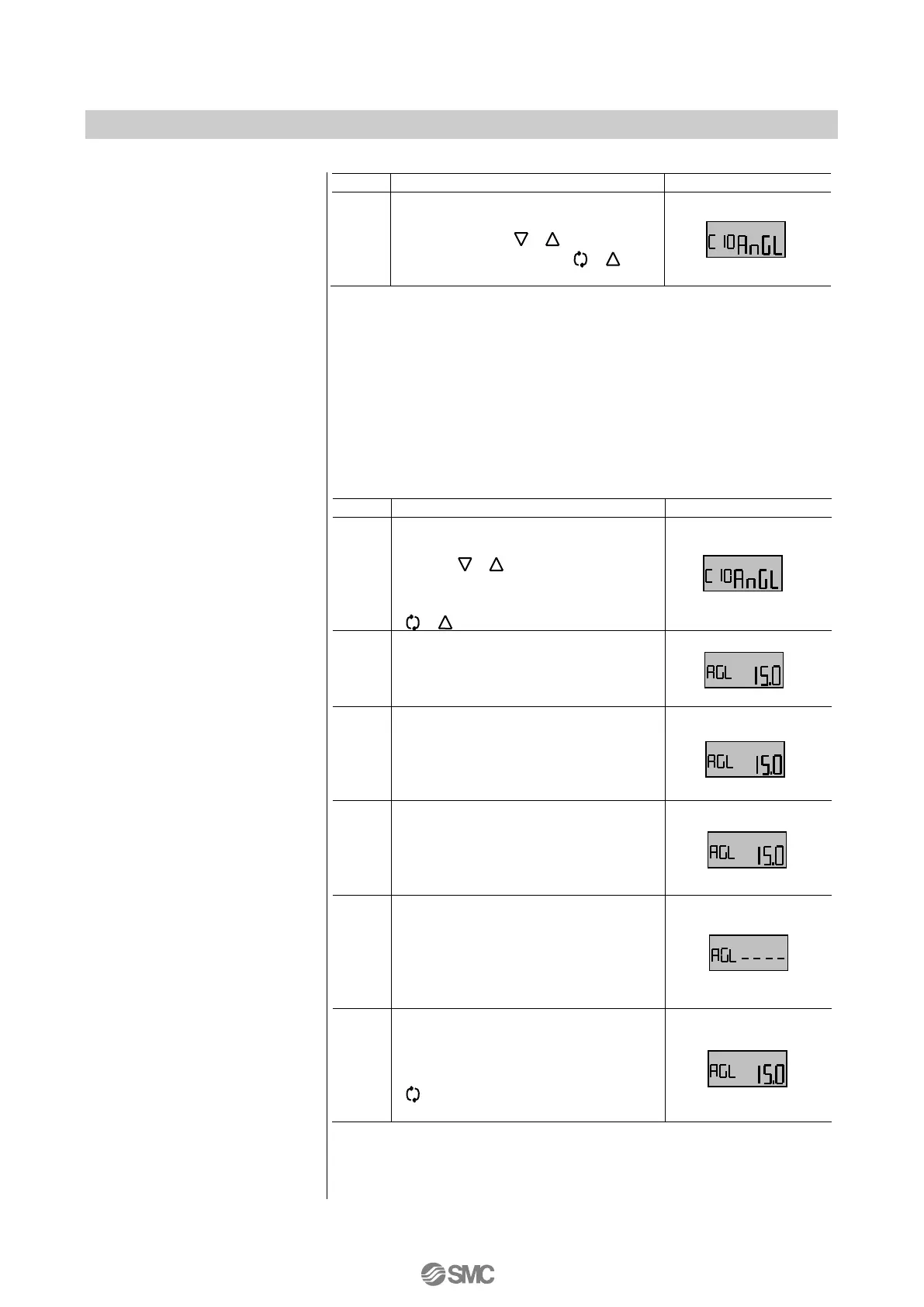
Apply the input current and supply
pressure, press the UP or DOWN
button ( ) in calibration mode
to select the angle (AnGL), and
then hold down the set button
( ) for 1sec or longer.
The output of OUT1 is 0MPa
*5
, and
the valve stem is located at the end
position. Check the value on the
LCD display is between -30 and 30.
Rotate the pilot valve unit
auto/manual switching screw
approx. 1/8 turn to the manual side
paying attention to the actuator
operation
*6
.
OUT1 output reaches its maximum
and the valve stem is located at its
end position opposite the one in
clause 2. Confirm the LCD shows a
number between -30 and +30.
If the LCD displays shows bars
(----), indicating that the value
exceeds +/-30 at the end position,
readjust the position of the
positioner so that the angle is within
the specified range.
After confirmation, rotate the
auto/manual switch screw to the
auto position and tighten it securely.
Then, hold down the mode button
( ) for 1sec. or more to return to
calibration mode selection screen.
Select the parameter used in
section 2 to 5 by pressing the UP or
DOWN button ( ) and holding
down the set button ( ) for
1sec or longer.
 Loading...