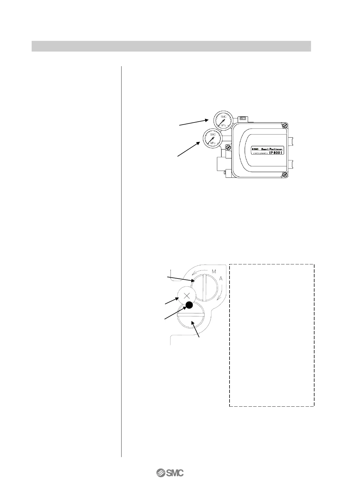
6: Auto and manual mode can be switched by rotating the pilot valve
unit auto/manual switch screw to the manual (M) side as shown in
Fig. 17. A small stopper screw in the top is to prevent loosening and
must not be tampered with or loosened. Also, a sensitivity holding
screw is set prior to factory shipment and must not be accidentally
rotated.
4: The positioner standard stroke is a rotational angle of 10 to 30
o
. An
Installations condition with a rotating angle of less than 10
o
or over
30
o
is not available.
5: A Description of pressure gauges mounted on the positioner are as
shown in Fig. 16.
- Be sure to normally tighten
the screw to the auto side
(A) when the positioner is
operated with an input
current.
- Supply pressure and the
OUT1 output are connected
by rotating the Auto/Manual
changeover screw towards
M.
Manual stroke adjustment
of the diaphragm valve and
single acting actuator can be
adjusted by using the supply
pressure setting reducing
valve Mode switching is
available by approx. 1/8 turn.
Keep the rotation within 1/4 to
1/8 turn.
 Loading...