A-7
Front Attachment
45-005 HYDRAULIC SAND PLOW INSTRUCTIONS
A port, B port, IN
port and OUT port� Reference Single Bank Hydraulic Valve Drawing for a detailed view of the valve�
7� Thread two,
3
/
8
B
the A port�
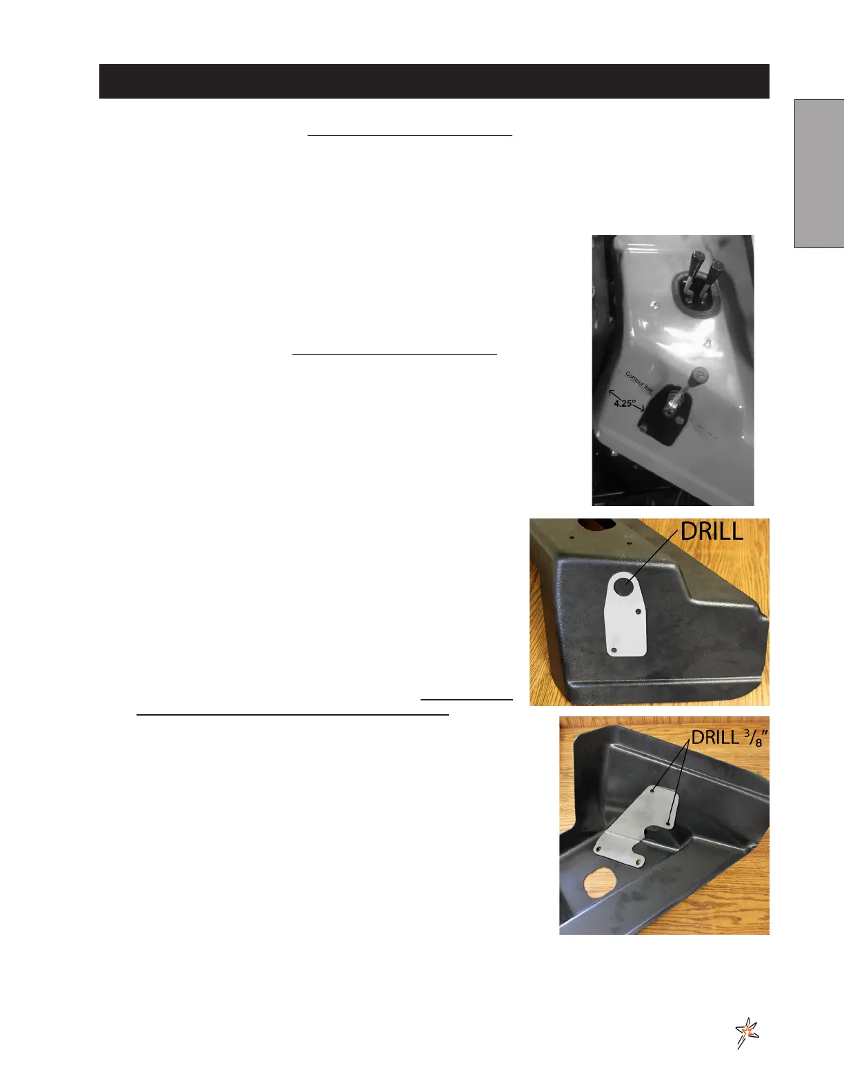
9� Fiberglas Fender: Using the valve mount as a template, Measure in approxi-
mately 4�25 inches from edge of right fender and mark� Line valve mount up
with contour of the fender and the right side of the line you just marked� Trace
-
ing holes out�
10� Fiberglass Fender: Mount the single bank hydraulic Valve (Ref# 22) to the valve
mount (Ref# 19) as illustrated, using the two ¼ - 20 x 2 bolts (Ref# 20)� Secure
21) to the valve� Reference Single Bank Hydraulic Valve Drawing for a detailed
view of the valve�
11� Plastic Fender: The Valve assembly mounts on the right front fender� The Valve
goes underneath the fender with the handle pointing outward� The Valve Mount
Plate (Ref 19) mounts on the outside of the fender� The Valve Brace (Ref 28)
mounts inside the fender�
12� Plastic Fender: Remove the 4 bolts holding the fender to the mainframe� Work-
ing on the inside of the fender, place the Valve Brace, with the slotted holes
front of the fender, as shown in the photo� Mark the location of the
3
/
8
" hole at each mark� Use a piece of scrap
wood to drill into to prevent tearing the plastic fender.
13� Position the Valve Mount (Ref 19) so the holes line up with the holes
that you drilled� Mark location of the large hole then drill a 1¼" hole
at that mark� Use a piece of scrap wood to drill into to prevent tear-
ing the plastic fender.
14� Route the 43" hose (Ref# 24) from the B port on the single bank
hydraulic valve to the top port on the hydraulic cylinder� Route the
51�5" hose (Ref# 23) from the A port on the single bank hydraulic
valve to the bottom port on the cylinder�
15� Disconnect the negative (-) ground battery cable from the battery�
Place a drain pan under the valve on the machine� ENGINE MUST
BE COOL BEFORE DISCONNECTING THE HOSES�
16� Disconnect hose (Ref# 26) from the IN port on the two-bank hy-
draulic valve (Ref#25)� Connect this hose (Ref# 26) to the "P" port of the
single bank valve (Ref# 22)� Connect the 26" hose (Ref# 27) from the
"T" port on the single bank valve (Ref# 22) to the IN port of the two-Bank
valve (Ref# 25)� Fasten to the frame using the 14½" nylon ties�
17� Reconnect the negative (-) ground battery cable to battery�
18� Make sure that everything is clear of the machine� Start the machine,
work the valve so that the plow will both raise and lower� Also, do this with
both the attachment lift and the rake lift� Work the lift a number of times
until all air works out of the plow circuit and the cylinder works smoothly�
repair, start up and check again�
19� Check the hydraulic oil level� The level should be 2” to 2½” below the top
of the tank� If more is needed, use SAE 10W-40 API service SG motor oil�