8
SCHEMATICS AND BLUE PRINTS
After building the structures in this set, you may want to expand using parts from other brick construction and Snap Circuits
®
sets you
already have. For this, advance planning is recommended. Think about what you want your structure to do and how you want it to look
before you start building it. Electrical engineers make drawings of their circuits (called schematics), and architects make drawings for
their building (called prints or oor plans). Schematics and prints are also useful in analyzing problems or making changes after the
circuit or structure has been built.
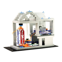
Electrical schematics use simple symbols to represent the
electrical components, often the same symbols that are marked
on your Snap Circuits
®
components. Wires are represented by
just lines and can be of any length. This is a schematic for the
circuit in project 11:
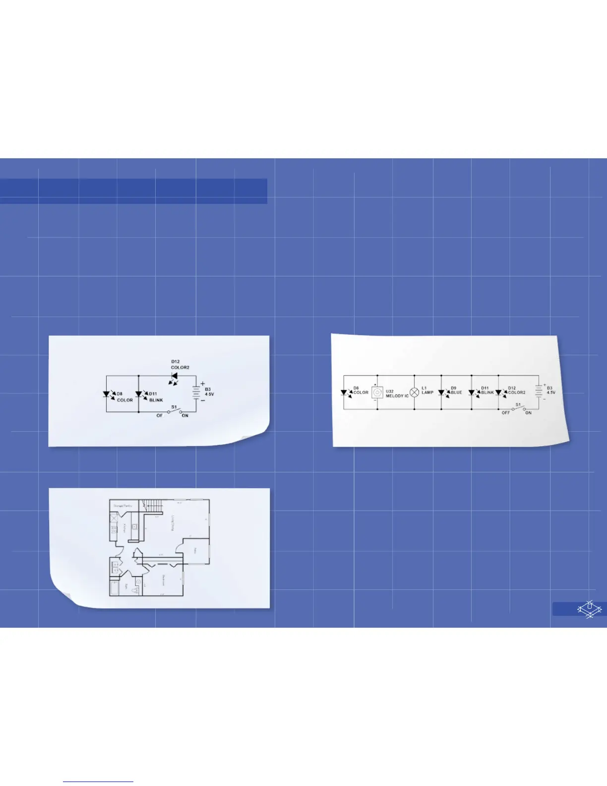
This is a schematic for the circuit in projects 2, 7, 8, 12, 13, and
TBD; although those circuits are all constructed dierently,
electrically they are the same, with D8, D9, D11, D12, L4, and U32
all connected in parallel:
Schematics tell you how a circuit will work, but not how it is constructed. Similarly an architect’s print or oor plan of a house tells you
about the layout of the house, but not colors or other details. Here is an example of a oor plan drawing for a house:
An architect’s drawings may show the oor plan or other
information about the construction, depending on who will be
using the drawing. These drawings used to be call blueprints,
due to the color used when making them years ago. Notice that
the symbol for a switch in electrical schematics is based on the
architect’s symbol for a door.