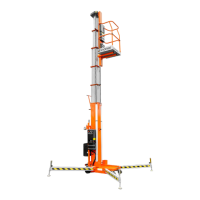
Page 2 - 14 UL25/UL32/UL40
OPERATION
Before operating the work platform, ensure that the pre-operation safety inspection has been com-
pleted and that any deciencies have been corrected. Never operate a damaged or malfunctioning
machine. The operator must be thoroughly trained on this machine.
NOTE: The platform will not elevate unless all 4 outriggers are properly installed with screw
jack pads rmly in contact with the oor and each outrigger indicator lamp lit. The chassis
is level to 1.0 degrees or less in all directions.
1. AC units: Connect the power unit plug to an approved extension cord.
2. DC units: Verify that the battery charger is turned off and that the extension cord is removed.
3. Pull the chassis emergency stop switch to the ON position.
4. Turn the key to platform.
5. Enter the platform by raising the drop bar.
6. Ensure the drop bar falls freely to its lowered position.
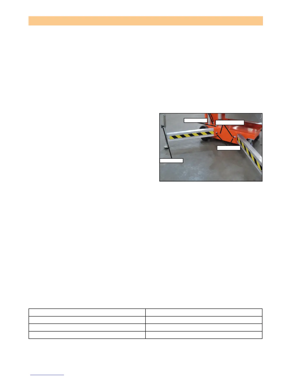
OUTRIGGER INSTALLATION
1. Remove the outriggers from the storage locations
on the sides of the mast.
2. Insert the outriggers into the outrigger socket at the
base.
3. Ensure the locking pin engages with the hole at the
end of the outrigger. Pull the outrigger outwards to
ensure it is engaged.
4. Repeat step 3 for the rest of the outriggers. Make
sure all 4 locking pins are engaged.
5. Level the base, centring the bubble in the orbit
level on the base by adjusting the screw jacks (turn
clockwise) at the end of each outrigger. Do not
release the tension (turn counterclockwise) on an
outrigger to level the base.
6. All 4 screw jack pads must be in solid contact with
a rm surface and each outrigger indicator light must be lit before the platform is elevated.
PLATFORM ELEVATION
1. Check that the area above the platform is clear before elevating the platform.
2. Pull the platform emergency stop switch to the ON position.
3. Push both the middle and the top buttons (enable and up) on the control box at the same time
to elevate the platform. Release the buttons to stop.
• In the event of an emergency, push the emergency stop button.
4. Visually inspect the mast assembly for cracked welds and structural damage, loose hardware,
hydraulic leaks, loose wire connections and erratic operation. Check for missing or loose parts
PLATFORM LOWER
1. Check that the area below the platform is clear before lowering the platform.
2. Push both the middle and bottom buttons (enable and down) at the same time to lower the
platform. Release the buttons to stop.
BATTERY CONDITION LED
The battery condition LED illuminates to give an approximate indication of the amount of charge
left to be used as follows:
Not illuminated 100% to 40%
Slow ash 40% to 20%
Fast ash 20% to 10%
Steady on less than 10%
NOTE: To maximise battery life, always re-charge the battery after use and never store the
machine for extended periods without rst fully re-charging the battery.
Figure 2-6: Outrigger installation
components
Table 2-1: Battery condition indicators.
Screw jack
Bubble level
Indicator lights
Locking pin