NETYS RT 5 - 7 - 9 - 11 kVA - 551570A - SOCOMEC
73
EN
NRT3-OP-PMB
TO UPS PARALLELTO UPS PARALLEL
TO UPS-1 OUTPUT
BYPASS MODE
UPS MODE
UPS-2UPS-1
OUTPUT BREAKERBYPASS BREAKER
WARNING:
ONLY AUTHORIZED SERVICE PERSONNEL
CAN REMOVE THIS COVER PLATE.
REMOVING THIS COVER PLATE WILL CAUSE
THE INVERTER TO SHUTDOWN. SEE THE
USERS MANUAL FOR INSTRUCTIONS.
4
9
10 10
3
8
TO UPS-1 INPUT
TO UPS-2 OUTPUT TO UPS-2 INPUT
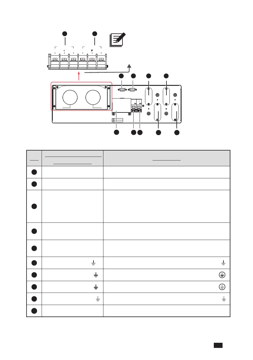
NOTE :
Remove the terminal
cover plate and you will
see the wiring terminal
blocks.
N(L2)
OUTPUT
AC I NPUT
N(L2) L(L1) L(L1)
N L
N L
N L
N L
INPUTOUTPUT
No.
Item (Printed Words on
the Front Panel)
Connection
1
AC Input Connects to the main AC utility.
2
Output Connects to the critical loads.
3
Bypass Breaker
No connection is needed. After you remove the two
screws shown in
Figure 15
to remove the cover
plate, the PMB’s detector will automatically activate
and send a message to the UPS to ask it to transfer
into bypass mode.
4
UPS-1 Output Breaker
No connection is needed. The function is to prevent the
output terminals from damage caused by overload.
5
UPS-2 Output Breaker
No connection is needed. The function is to prevent the
output terminals from damage caused by overload.
6
To UPS-2 Output (L/ N/ )
Connects to the UPS2’s UPS Output terminals (L/ N/ )
7
To UPS-2 Input (L/ N/ )
Connects to the UPS2’s AC Input terminals (L/ N/ )
8
To UPS-1 Input (L/ N/ )
Connects to the UPS1’s AC Input terminals (L/ N/ )
9
To UPS-1 Output (L/ N/ )
Connects to the UPS1’s UPS OUTPUT terminals (L/ N/ )
10
To UPS Parallel Connects to the UPS’s parallel port.
 Loading...